3. Configuration
This guide has the instructions to configure and use a Flows project.
Flows Configuration
Configuration of a Flows project requires the following steps:
- Name the project.
- Start the project.
- Design & Deploy your flows.
- Import or Export flows and nodes.
A full example can be found in the example section below.
The following sections describe each activity.
Setting the Project Name
The first step in configuring a new Flows Project is to give it a name.
In the Project tab:
- Enter a name for the project.
- Set switch to Manual mode if you do not want the project to start automatically when Edge One™ starts.
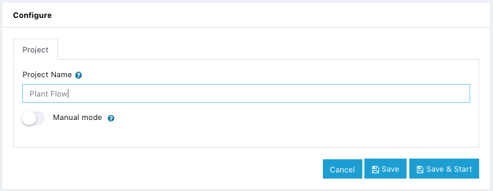
- Click Save to simply save the project or Save & Start to run the project. In both cases, you will be returned to the project’s main page.
The results of a Save are shown below.
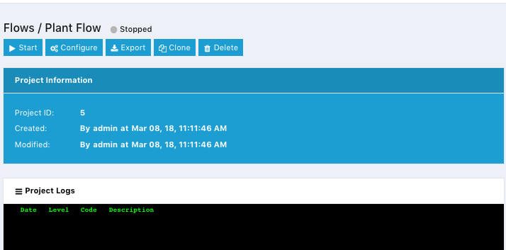
- You need to Start the project, next.
Start the Flows Project
To use the Flows visual designer, your Flows project has to be started.
- Click on Start.
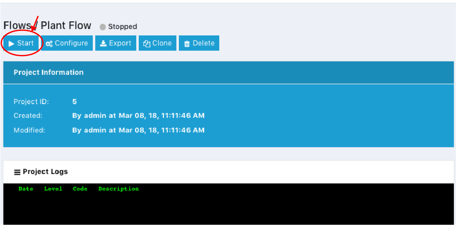
- Design your flows next.
Designing and Deploying Flows
Once your project is running, you can start to design your flows as follows:
- Click on Manage Flow to open the design page of Flows.
-
Add nodes to the workspace and wire then together.
-
The design page includes five areas:
- The design workspace where you build your flows.
- The Top Bar with the main menus.
- The Palette with the available nodes.
- The sidebar which is optionally displayed and shows node information, debug connector broker configuration.
- The bottom bar which allows to collapse the palette menu and to zoom in/out the design board.
Design workspace
The design workspace includes a grid on which to place nodes. Nodes have connector globes that are used to wire them together.
To design a flow:
- Select a node from the palette.
- Drag and drop the node into the workspace.
- Add another node in the same way.
- Wire them together by clicking on the connector globe of the source and dragging to the target node.
- When finished, click on Deploy.
For more details see the example below.
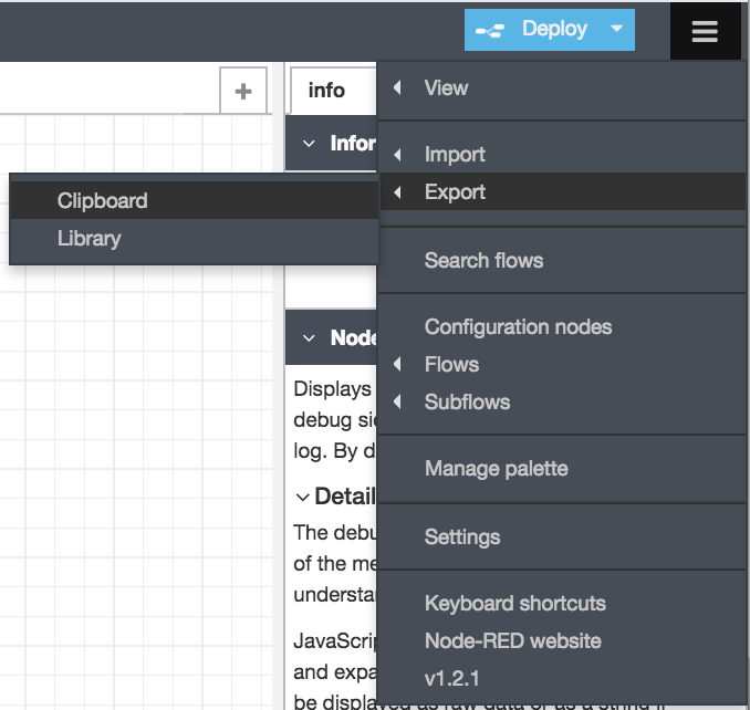
Top Bar Functions
The top bar of the Flows interface includes the following functions:
- Make full screen button which will make the design space the size of the display’s screen.
- Deploy dropdown menu. It allows to select the deployment method to be used. The choices are:
- Full which deploys everything in the workspace.
- Modified Flows which only deploys flows that contain changed nodes.
- Modified Nodes which only deploys nodes that have changed.
- The Menu Bar which includes the following items:
- View - Allows to display the information sidebar or not.
- Debug messages - Displays debug messages on the debug tab on the sidebar.
- Import - allows to import entire flows or nodes to the current flow or to a new flow, and also allows to import devices from a Library.
- Export - allows to export nodes or flows.
- Search flows - allows to search for flows.
- Configuration - Opens the config tab in the sidebar which allows to configure the connector-broker on all flows or a single flow.
- Flows - Allows to add new flows, to rename a flow or to delete a flow.
- Subflows - Allows to create a subflow which is opened on a separate design tab.
- Manage palette - Allows to:
- View - Allows to configure the design gris, the display of node status and whether to show tips.
- Palette - allows to manage the existing nodes in the palette and to install new nodes.
- Keyboard - allows to configure keyboard shortcuts to speed up the development process.
- Settings Same functionality as Manage palette.
- Keyboard Shortcuts Same menu as manage palette.
- Node-RED website is a link to the Node-RED website.
- v1.2.0 is the CloudPlugs version of the Flows engine. Clicking displays the version of Node-RED it is based upon.
Importing Flows and Nodes
To import a flow or node:
-
Open the source workspace either in a Flows project or in Node-RED.
-
Select the individual node(s) or all the nodes in the flow.
-
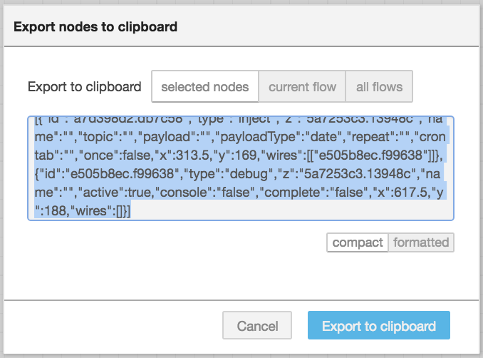
On the menu bar, select Export->Clipboard.
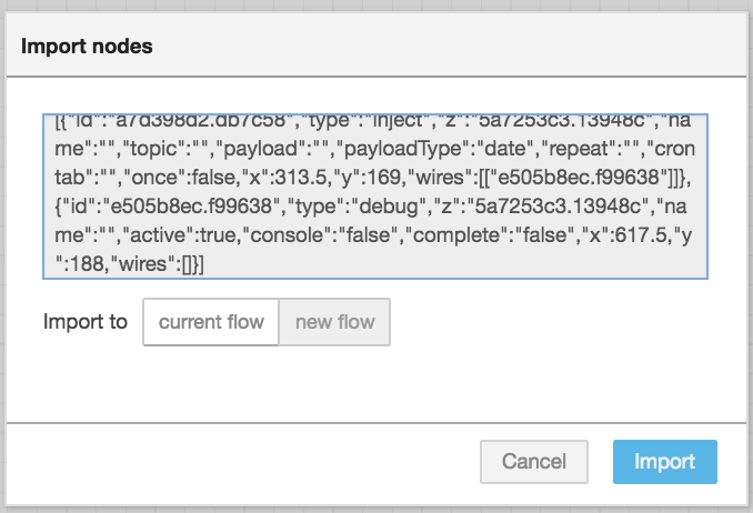
The export window will open with the JSON of the selected nodes as shown below.
-
Click on Export to Clipboard. It is recommended that you save the Clipboard contents to a file.
-
Open your target Flows project and click on Manage Flows to open the project workspace.
-
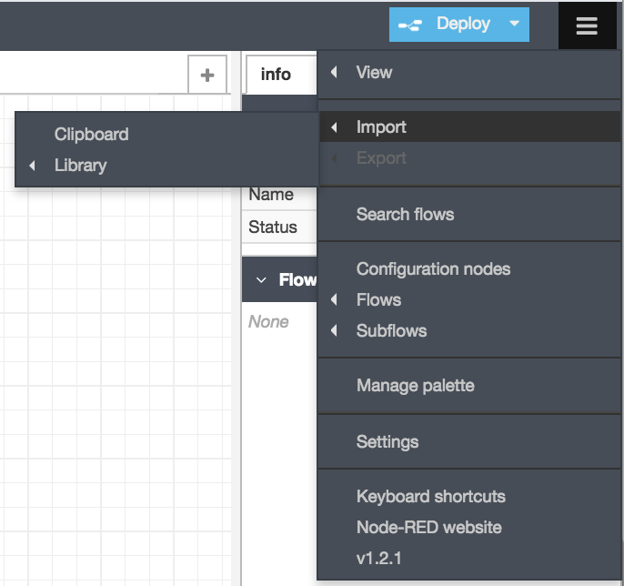
On the menu bar, select Import->Clipboard.
-
Make sure that the desired nodes are copied into your system’s Clipboard and Paste them on the import space.
-
Select either the current flow or a new flow.
-
Click on Import to complete the procedure.
Exporting Flows and Nodes
To export a flow or node:
-
Open the source workspace either in a Flows project or in Node-RED.
-
Select the individual node(s) or all the nodes in the flow.
-
On the menu bar, select Export->Clipboard.
The export window will open with the JSON of the selected nodes as shown below.
- Click on Export to Clipboard. It is recommended that you save the Clipboard contents to a file.
Palette of available nodes
The palette shows the list of available nodes that can be used to create flows.
Sidebar
The sidebar includes the following:
- Info tab displays:
- Information a summary of the nodes characteristics such as their id, type, connector, module, pid (project id) and others.
- Flow Description which includes details on the parameters required by the node and its main features and expected behavior. The level of details depends on what the node developer decided to include with the node.
- Debug displays any message generated by a Debug node. By default, it just displays the payload of the message, but it is possible to display the entire message object.
- Config displays all the configuration nodes available on all flows or single flows.
Bottom Bar
The bottom bar allows to:
- Expand and collapse the palette menus.
- Zoom in/out of the workspace.
Configuration example
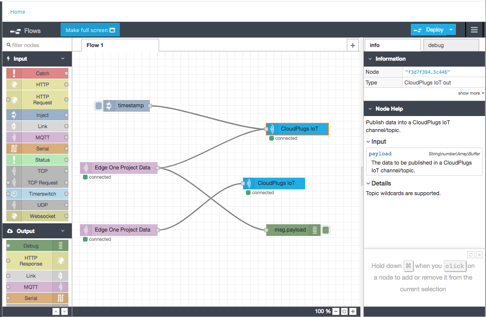
Here is a simple configuration example. We want to get data from an Edge One™ Modbus project and send it to CloudPlugs IoT. In addition, we will add a debug node and inject node to initiate the flow with its default timestamp. The inject node will be used to allow to trigger the node manually by clicking on its button within the editor.
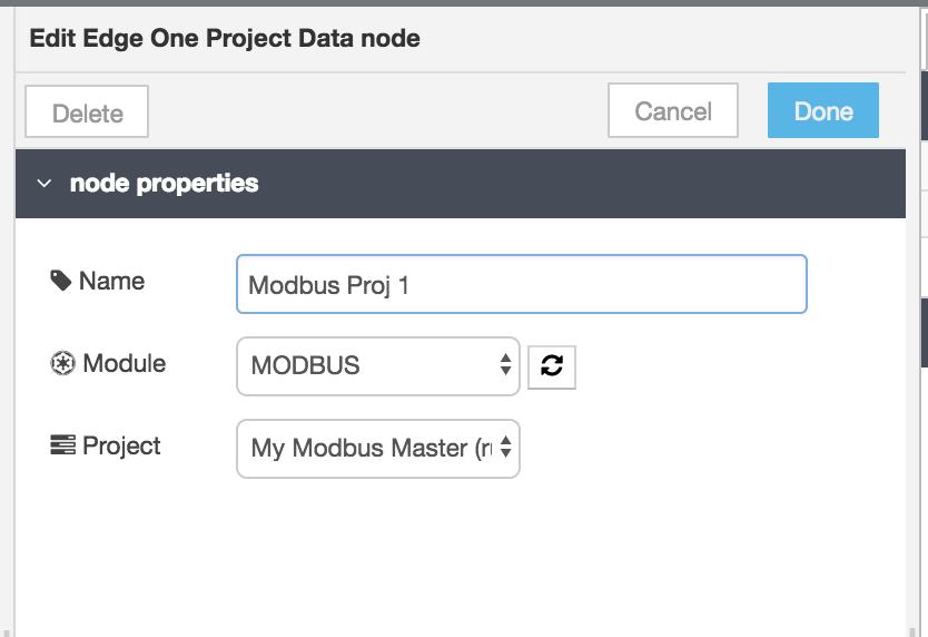
- Drag and drop an Edge One™ Project input node into the workspace.
- Configure the node:
- Double click on the node to open it.
- Enter a name for the node.
- Select the Modbus module from the module list.
- Select the project that data will be read from.
- Click on Done.
- Drag and drop a CloudPlugs IoT output node into the workspace.
- Configure the node:
- Double click on the node to open it.
- Enter a name for the node. The default name for the node, if no name is entered, is the CloudPlugs IoT URL and port api.cloudplugs.com:1883.
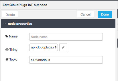
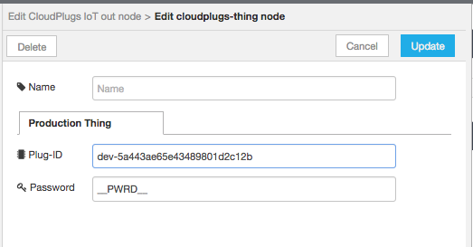
- Click on edit ( )to enter the Plug-ID and connection password for the Thing that will be used to send data to CloudPlugs IoT.
- Enter the topic or channel where the data will be written.
- Click on Done.
- Connect the Edge One™ input node to the CloudPlugs IoT output node.
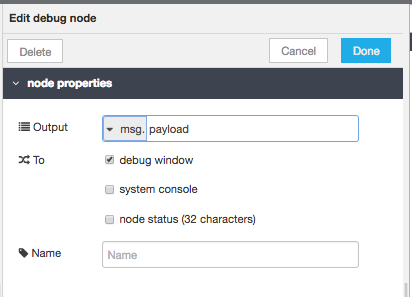
- Drag and drop a Debug output node.
- Configure the node:
- Enter a name for the node.
- Select the output. It can be the message payload only or the entire message object. We select only the payload for this example.
- Select the target for the debug output. We selet the debug window of the sidebar.
- Optionally enter a name for the node. If left blank the default name will be used which in this case is msg.payload.
- Click on Done.
- Connect the Edge One™ input node to the debug output node. The debug information will be displayed in the debug tab of the sidebar.
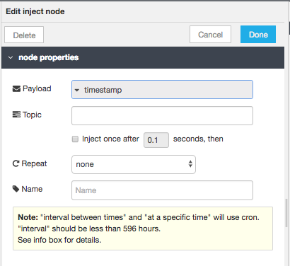
- Drag and drop an Inject output node. We use this node to initiate the flow with the default payload value which is a timestamp of the current time in milliseconds. By default, the node is triggered manually by clicking on its button within the editor.
- Configure the node:
- Enter a name for the node. Here we called it timestamp.
- We leave the other fields empty since the purpose is to use it to simply start the flow by clicking on the node.
- Click on Done.
- Connect the inject node to the the CloudPlugs IoT output node.
The resulting flow is shown below. It has an additional flow that sends data from another OPC UA project on the Edge to another topic in CloudPlugs IoT.