3. Configuration
This guide has the instructions to configure and use a Message Router project.
Message Router Configuration
Configuration of a Message Router project requires the following steps:
- Set the Project basic parameters.
- Configure the available source and sink message brokers.
- Input or configure any filter functions.
- Configure the routes.
The following sections describe each activity.
Setting the Project Basic Parameters
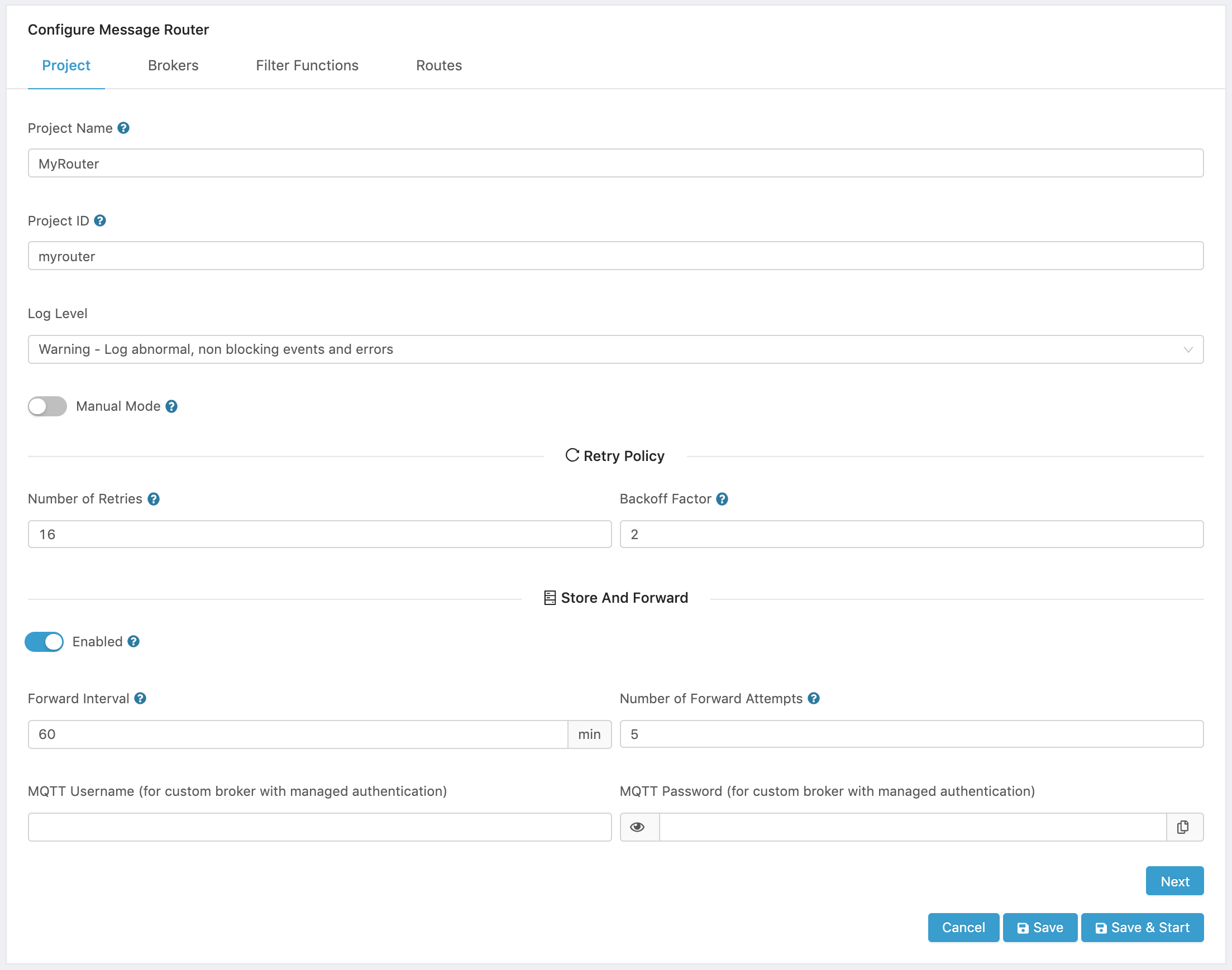
The first step in configuring a new Message Router Project is to give it a name and set up its basic operation parameters. These parameters allow to configure the Retry and Store and Forward policies. The Message Router tries to send the data based on the retry policy. If Store and Forward is enabled, it will try to forward the data based on a user configured interval. Every attempt to forward data is governed by the retry policy configured. Then it is possible to configure the number of attempts to forward the data.
In the Project tab:
- Enter a name for the project.
- Enter a Project ID for the project.
- Set the log level that you want to have in the project.
- Silent - No logs will be printed on the console. This is the default log mode.
- Error - Reports only important and blocking errors that can cause malfunctions.
- Warning - All warnings for abnormal, non-blocking events as well as Errors will be reported in the logs.
- Info - All messages relevant to the current system status as well as Warnings and Errors will be reported in the logs.
- Debug - Full verbose mode. All errors, warnings, and information will be reported on the log console.
-
Set switch to Manual mode if you do not want the project to start automatically when Edge One™ starts.
-
Set the Retry Policy.
-
*Enter the number of retries that the router will attempt to send data before storing it.
-
Set the backoff factor. The backoff factor to apply between attempts after the second try (most errors are resolved immediately by a second try without a delay). The formula that determines the sleep time between retries in seconds is:
   time between retries (sec) = 0.010 * Random * (backoff factor) ^ retry-attempt

   where, Random is a number between 0 and 1 and retry-attempt is the current attempt number which is incremented until the total number of retries is reached.
-
-
Set the Store and Forward parameters.
- To enable Store and Forward, set the Enabled switch to ON.
- Set the Forward interval in minutes. This is the time in minutes to wait before attempting to send all the stored messages.
- Set the Number of Forward Attempts.. This is the number of times that the entire process of sending and saving data will be attempted. Set to 0 to retry forever.
-
If the Edge One™ is configured with a custom or external MQTT message broker that has managed authentication and your Message Router project will use this broker, enter the broker’s MQTT authentication credentials:
- MQTT Username
- MQTT Password
-
Click Next to configure one or more available message brokers.
Configuring Message Brokers
The Message Brokers tab allows to configure one or more message brokers that will be used as data sources or sinks. There are two kinds of Message Brokers available as data sources or sinks:
- External Message Brokers which are any message brokers outside the Edge One™ Platform.
- Internal Message Broker which is the Edge One™ Internal MQTT Message Broker. Selection of this broker is only available to configure Routes.
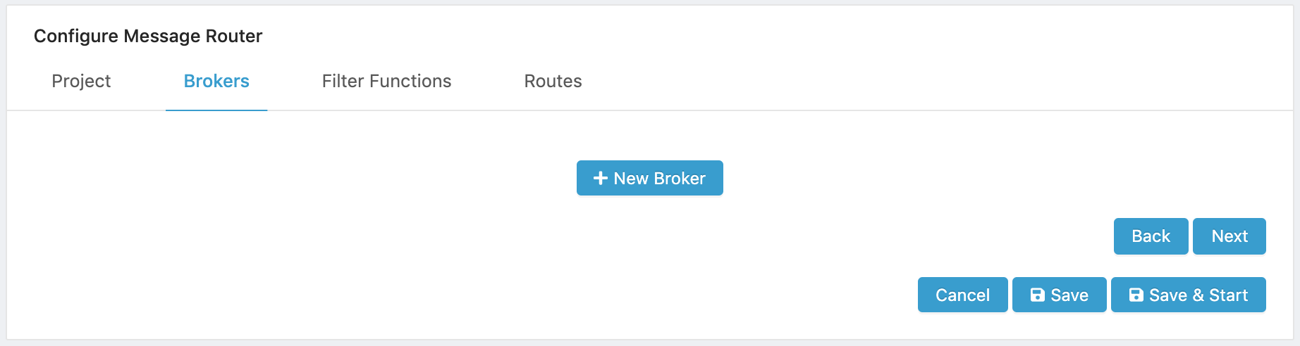
In the Brokers tab:
- Click on ( New Broker ).
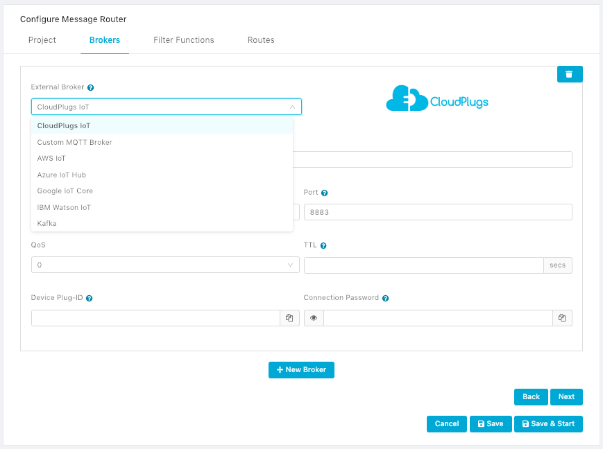
- Select an External Message Broker from the dropdown menu.
- Configure the Message Broker’s credentials and URI if required. The links below navigate to sections that indicate how to configure each of the available options.
- CloudPlugs IoT.
- Custom MQTT Message Broker.
- AWS IoT.
- Microsoft Azure IoT Hub.
- Google IoT Core.
- IBM Watson IoT.
- Kafka. This type of connection is typically required to send data to Cloudera, Hortonworks and other Hadoop-based data lakes.
Configuring CloudPlugs IoT as a Message Broker
The Message Router connects to CloudPlugs IoT using a TLS 1.2 over MQTT connection. To configure CloudPlugs IoT as the MQTT message broker:
- Create and enroll a Production Thing in the CloudPlugs IoT platform to use it to connect to the platform. The Production Thing’s Connection Credentials are required to create sink and source routes to CloudPlugs.
- Select “CloudPlugs” from the External Message Broker dropdown menu.
- Enter a name for the message broker or use the default CloudPlugs name.
- Set the URI for the Host of the connection. The default is mqtts://api.cloudplugs.com, but it could be different if CloudPlugs IoT is deployed on-premise.
- Set the TCP Port number for the connection. Default is 8883.
- Select the QoS (Quality of Service) level. CloudPlugs supports levels 0 or 1. QoS of 2 is not supported by the platform. The default is 0.
- Optionally, set the time-to-live (TTL) of the data in the CloudPlugs IoT platform.
- Enter the MQTT connection credentials.
- Plug-ID is the Plug-ID of the Thing representing the Edge One™ Message Router in the CloudPlugs IoT cloud.
- Connection Password is the connectivity password of the Thing representing the Edge One™ Message Router in the CloudPlugs IoT cloud.
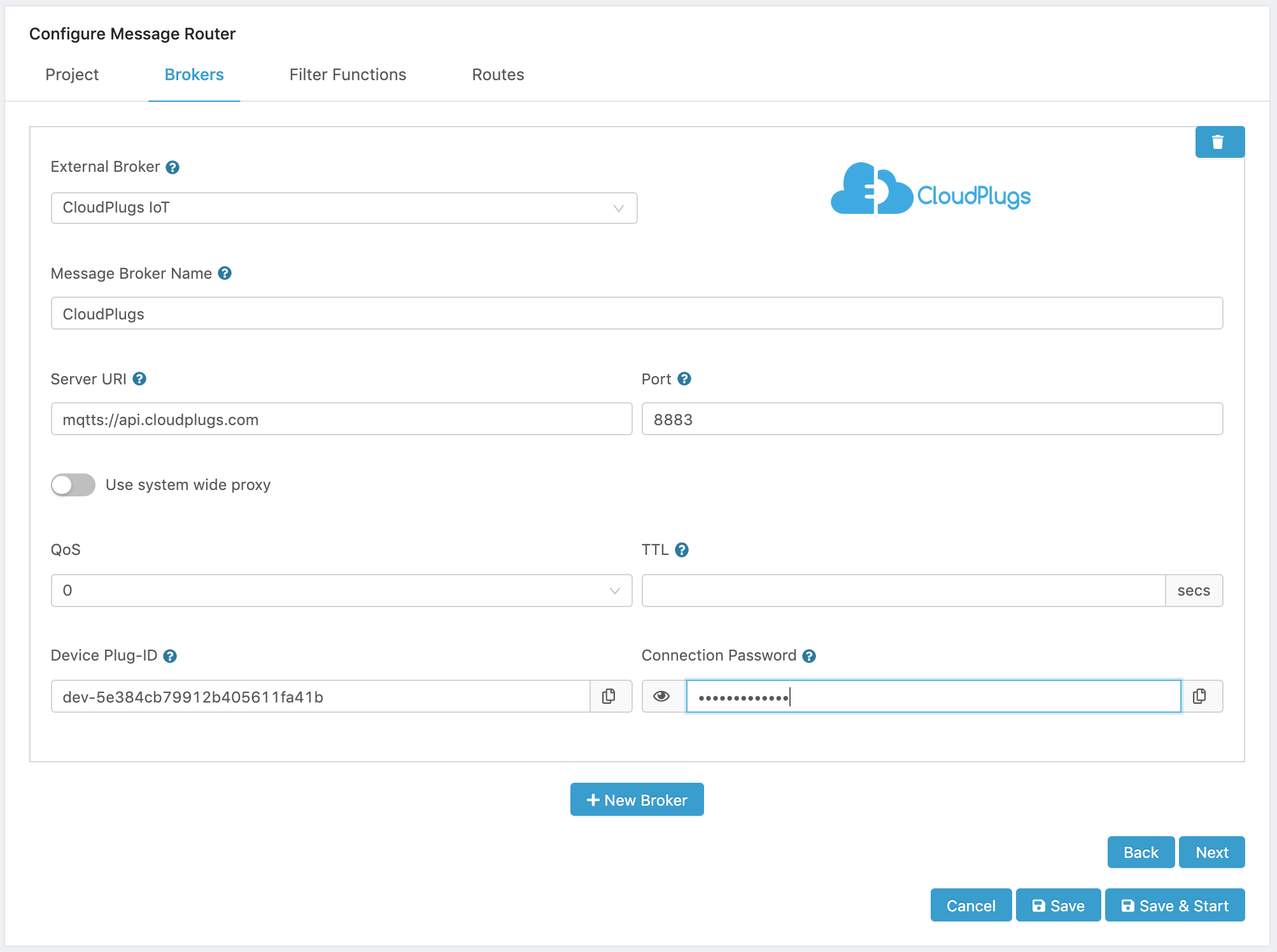
- Click Add Broker to configure another broker, or click Next to configure any data filter functions.
Configuring a Custom MQTT Message Broker
You can connect Edge One™ to any MQTT Message Broker of your choice. To configure a route to a custom MQTT Message Broker:
- Create and enroll a Production Thing in the CloudPlugs platform to use it to connect to the platform. The Production Thing’s Connection Credentials are required to create sink and source routes to the Message Broker.
- Select “Custom MQTT Broker” from the External Message Broker dropdown menu.
- Enter a name for the message broker.
- Enter the URI for the MQTT Broker host.
- Enter the TCP port to be used for the connection. Default is port 1883.
- Select the QoS (Quality of Service) level. CloudPlugs supports levels 0 or 1. QoS of 2 is not supported by the platform. The default is 0.
- Enter the MQTT connection credentials.
- User name is the is the user name credential for the MQTT connection.
- Password is the password credential for the MQTT connection.
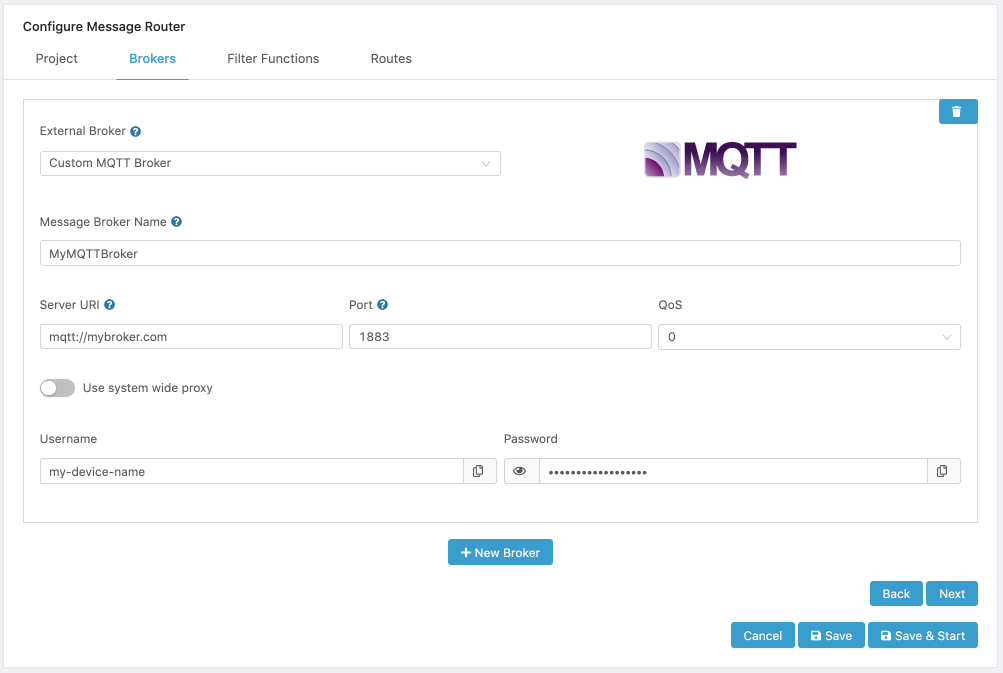
- Click Add Broker to configure another broker, or click Next to configure any data filter functions.
Configuring AWS IoT as a Message Broker
- Configure the device that will be used to connect to Amazon AWS IoT. The instructions to create and register an AWS IoT thing can be found in the AWS Developer Guide.
- Select “AWS IoT” from the External Message Broker dropdown menu.
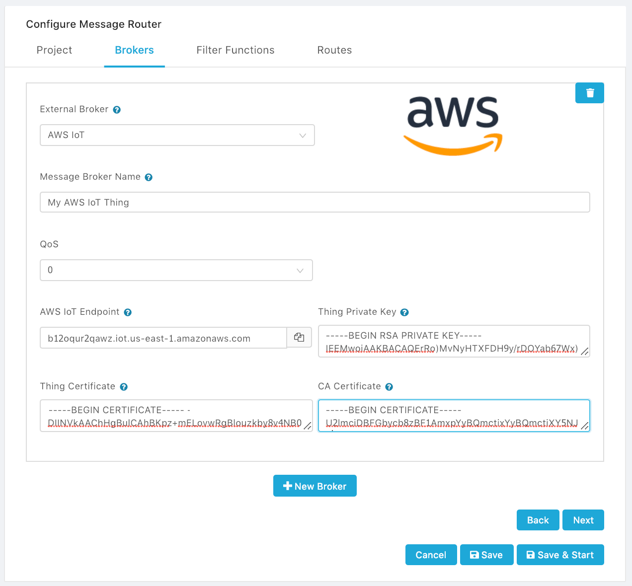
- Enter a name for the message broker.
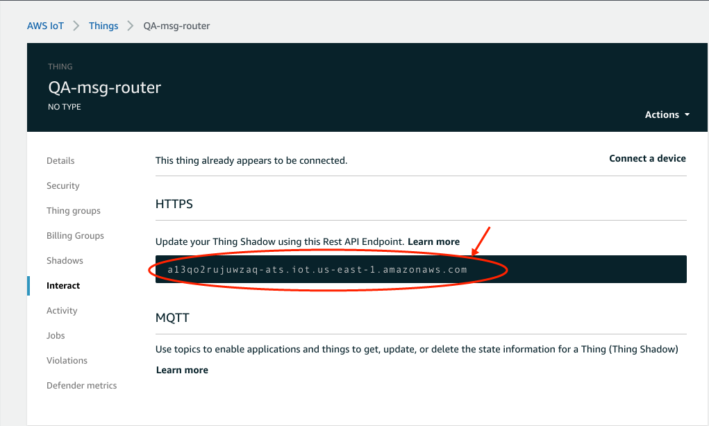
- Enter the AWS IoT Endpoint that was assigned to the device in AWS IoT. You can retrieve the Endpoint from the AWS IoT Thing -> Interact page.
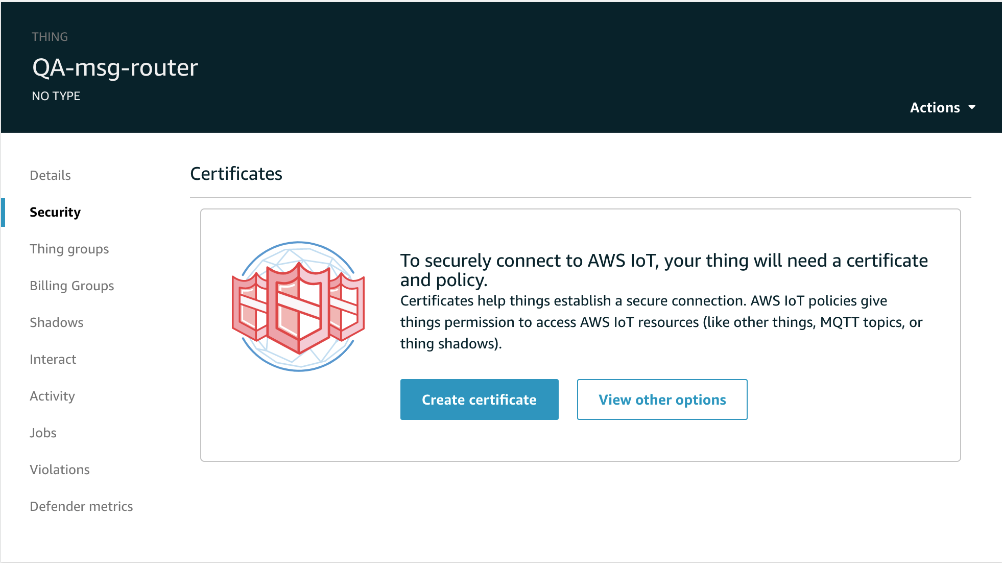
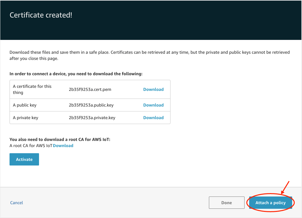
- Enter the certificates generated for the thing in AWS IoT. If you don’t have the certificates, generate them by clicking on Create Certificate in the Thing->Security tab.
- Enter the Thing Private Key that was assigned to the device. You can retrieve it after downloading it from the Thing -> Security -> Create Certificate page.
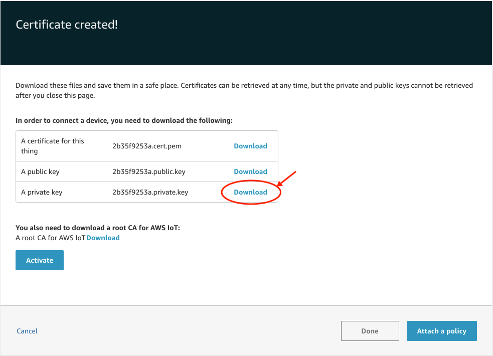
- Enter the Thing Certificate. You can retrieve it after downloading it from the Thing -> Security -> Create Certificate page.
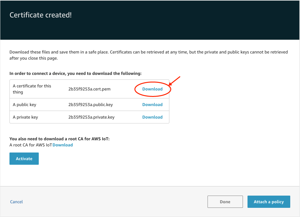
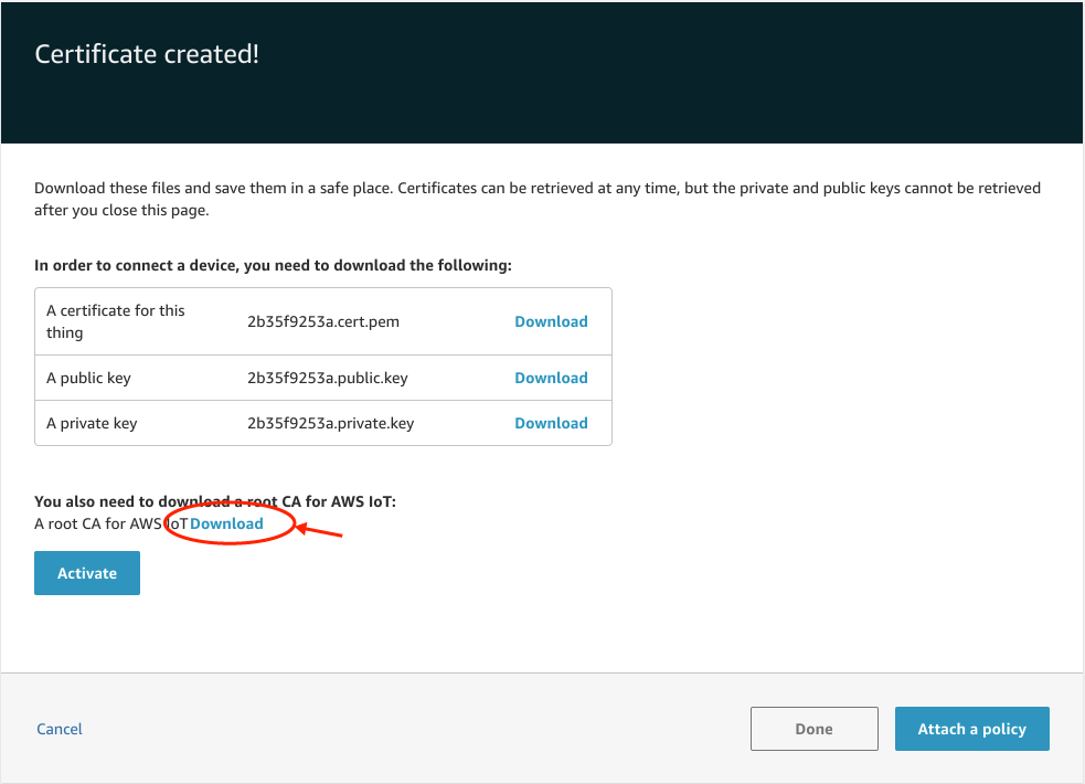
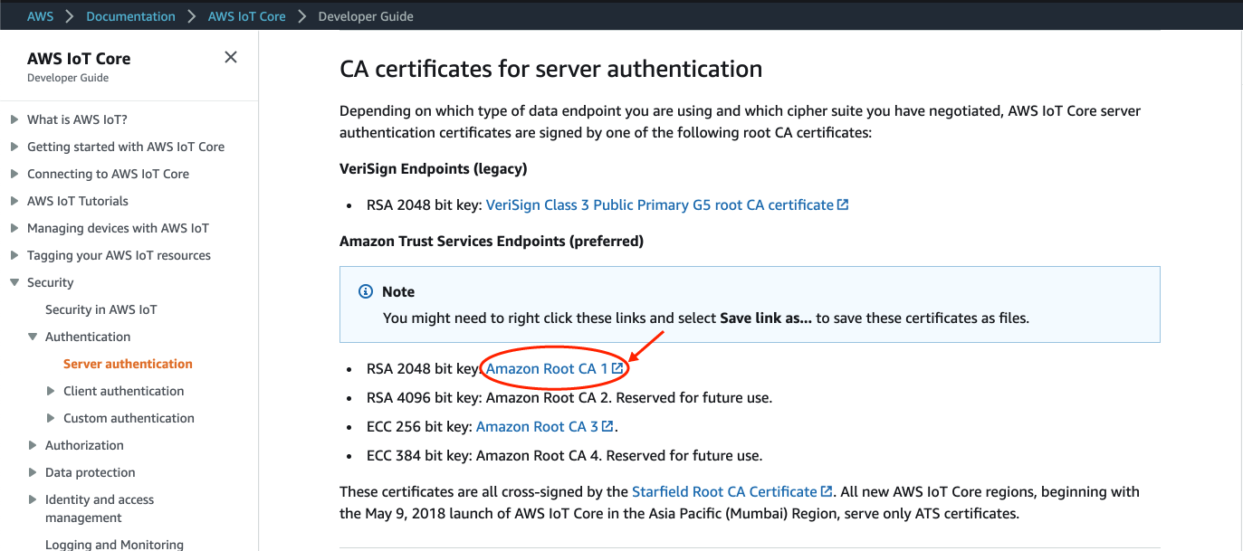
- Enter the CA Certificate. You can retrieve it clicking on Download it from the Thing -> Security -> Create Certificate page and selecting the certificate for your location from the CA certificates for server authentication page. For most applications using the RSA 2048 bit key: Amazon Root CA 1 will work.
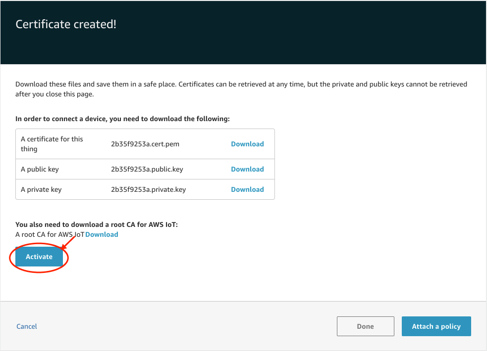
- Activate the certificates by clicking on the Activate button.
- Attach a Policy to the certificates by clicking on Attach Policy.
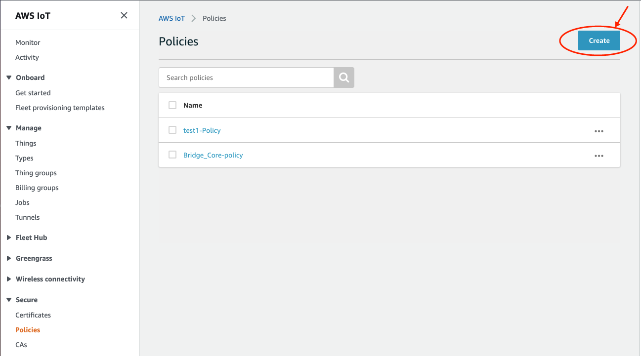
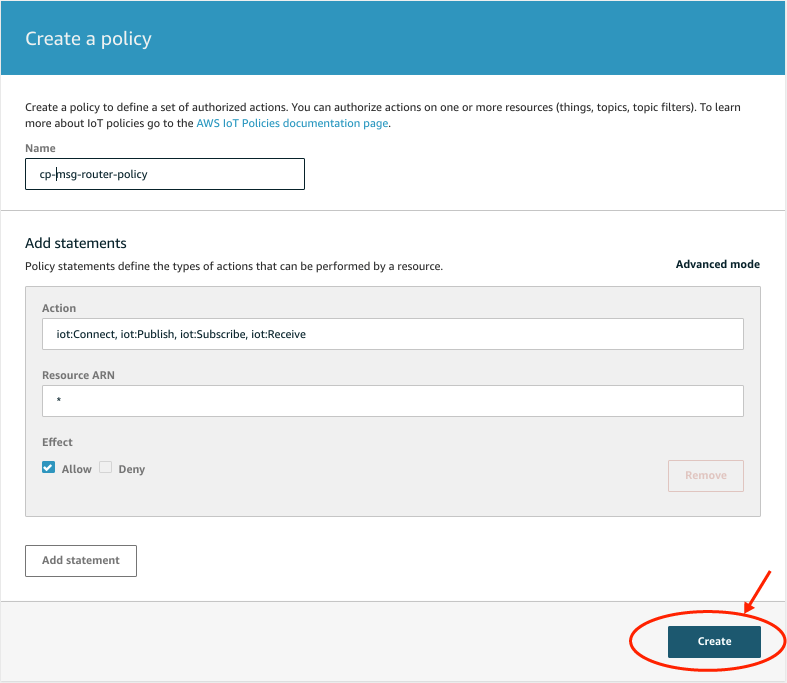
- Set and Select a Policy. You can create a new policy for your project. The minimum settings must include “iot:Connect” and “iot:Publish”. If you would like to be able to send commands to Edge One™ from AWS IoT also set “iot:Subscribe” and “iot:Receive”. For the Resource ARN, you can use the wildcard “*” or a specific resource.
- In the Policies page, click on Create to add a new policy.
- Enter the desired parameters for the policy and click on Create to save the policy.
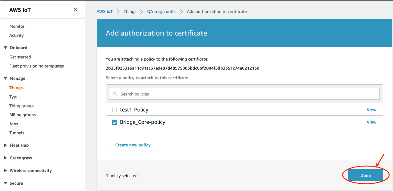
- Select your policy and click on Done.
The policy created will display on the list. In the example below, we just selected the available Bridge_Core-policy.
The configuration of the AWS IoT endpoint is now complete.
Here is a sample configuration for an Edge One™ AWS IoT Message Broker device.
- Click Add Broker to configure another broker, or click Next to configure any data filter functions.
Configuring Azure IoT Hub as a Message Broker
- Configure the IoT Device that will be used to connect to Azure. An example of how to do this can be found here.. The sections Create and IoT Hub and Register a new device in the IoT hub are the only two sections that must be read and followed to obtain the necessary parameters and credentials to configure the Message Router.
- Select “Azure IoT Hub” from the External Message Broker dropdown menu.
- Enter a name for the message broker.
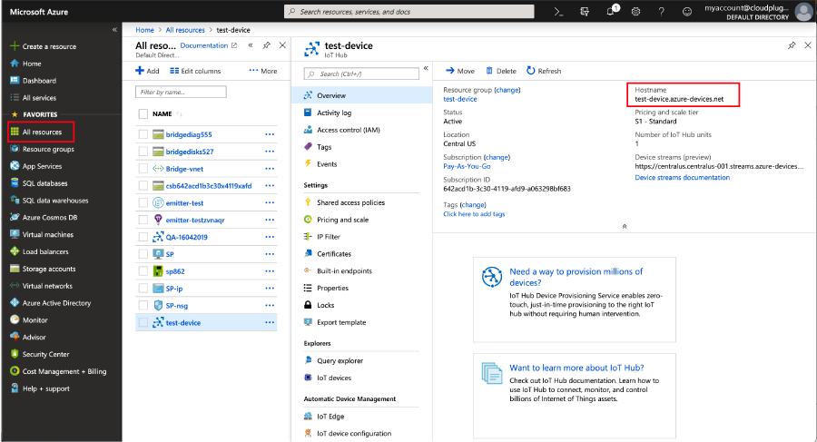
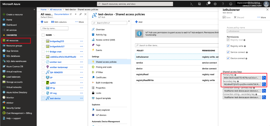
- Enter the Host Name that was assigned to the device in Azure. You can retrieve the hostname from the Device Overview panel in Azure (All resources > your-iot-hub-device > Overview > Hostname). Typically, the hostname has a structure such as hostname.azure-devices.net. See below.
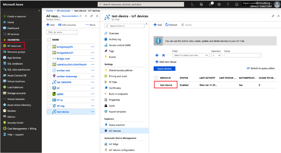
- Enter the Device ID that was assigned to the device. You can retrieve it from Device Details under the IoT Devices Explorer in Azure (All resources > your-iot-hub-device > IoT devices > DEVICE ID). See below.
- Enter the Shared Access Policy Name. The Policy Name is typically iothubowner which has all the permissions, but you can retrieve it by selecting your device and then Shared access policies in Azure (All resources > your-iot-hub-device > Shared access policies > iothubowner) as shown below.
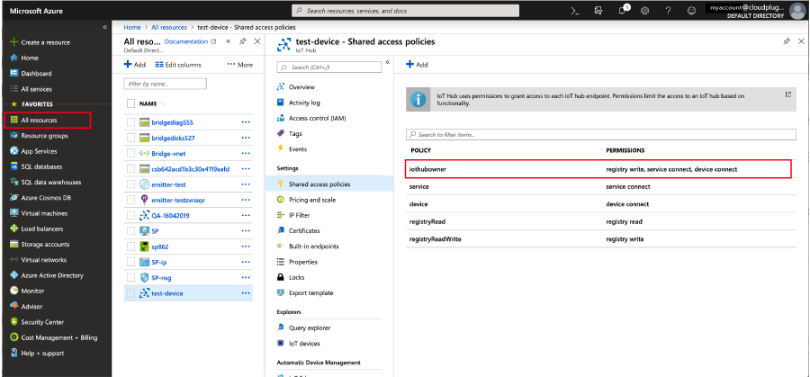
- Enter the Primary/Secondary Shared Access Key. Please note that the keys are entered into a single input field and they are separated by a “/”" You can retrieve them by selecting your device, then Shared Access Policies and double-clicking your policy name (All resources > your-iot-hub-device > Shared access policies > iothubowner) in the Azure portal. See below.
Here is a sample configuration for an Edge One™ Azure IoT Hub Message Broker device.
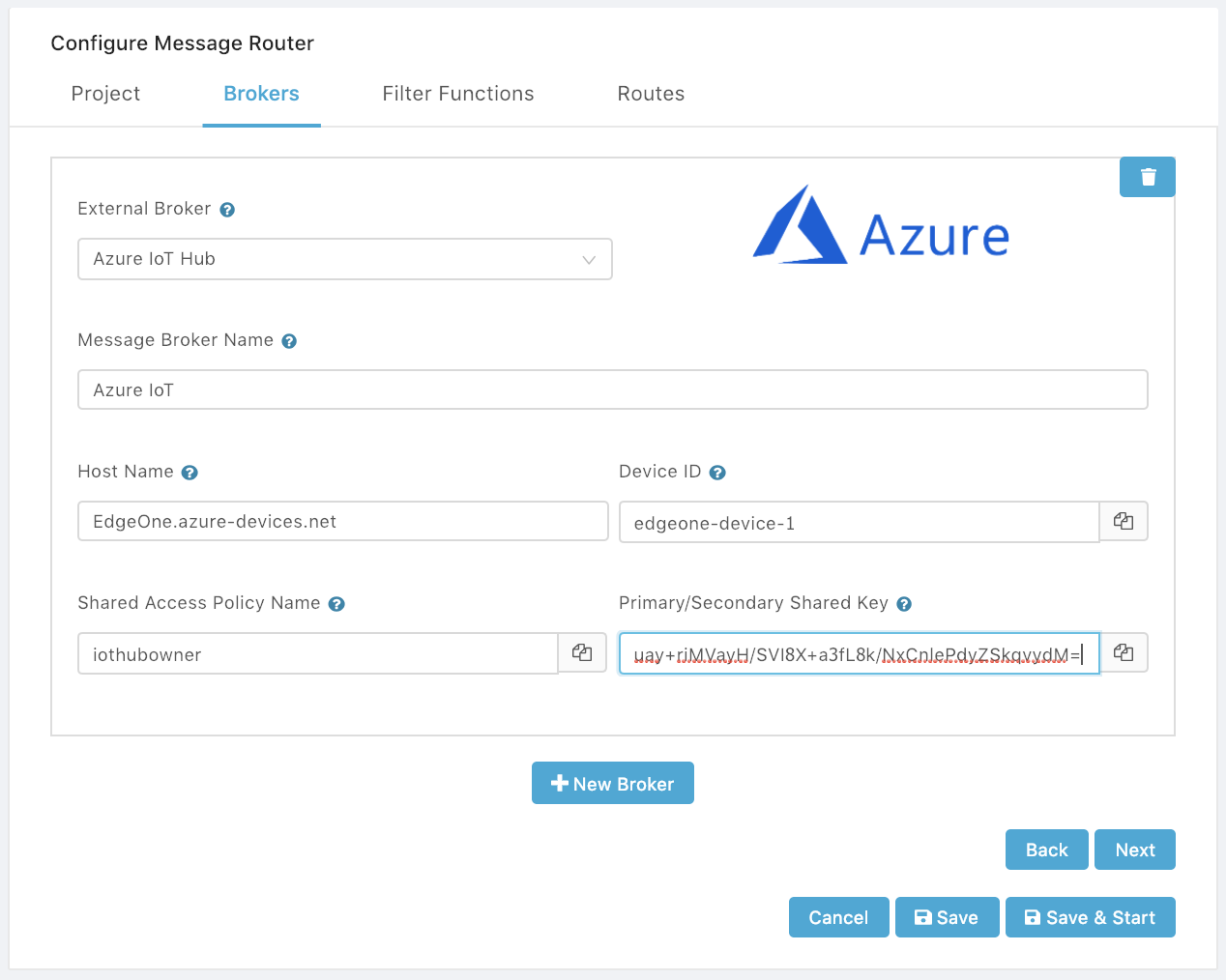
- Click Add Broker to configure another broker, or click Next to configure any data filter functions.
Configuring Google IoT Core as a Message Broker
The Google Cloud IoT Core service supports the MQTT protocol by running a managed broker that listens to the port mqtt.googleapis.com:8883. Port 8883 is the standard TCP port reserved with IANA for secure MQTT connections. Edge One™ connects to this port using TLS transport.
-
Configure the MQTT device connection that will be used to connect to Google IoT Core. The instructions to create and register a device can be found in the Getting Started section of the Google Cloud IoT Core documentation.
-
Select “Google IoT Core” from the External Message Broker dropdown menu.
-
Enter a name for the message broker.
-
Enter the projectID that was configured for the device. It is string ID of the cloud project that owns the registry and device.
-
Enter the GCP cloud region of the device registry, for example, us-central1.
-
Enter the Registry ID. The user-defined string identifier for the device registry, for example, registry1.
-
Enter the Device ID that was configured when creating the device registry in Cloud IoT. This is a user-defined identifier for the device, for example, thing1. This ID must be unique within the registry.
-
Enter the QoS or Quality of Service to be used for the connection. Only MQTT QoS of 0 and 1 are currently supported by Google IoT Core.
-
Enter the Algorithm which can be RS256 (RSA Signature with SHA-256) or ES256 (ECDSA using P-256 curve and SHA-256 Hash) for the encryption of the JWT (JSON Web Token) used to transmit the information as a JSON object.
-
Enter the Device Private Key assigned by Google Cloud IoT Core during the creation of the device.
Here is a sample configuration for an Edge One™ Google IoT Core Message Router device.
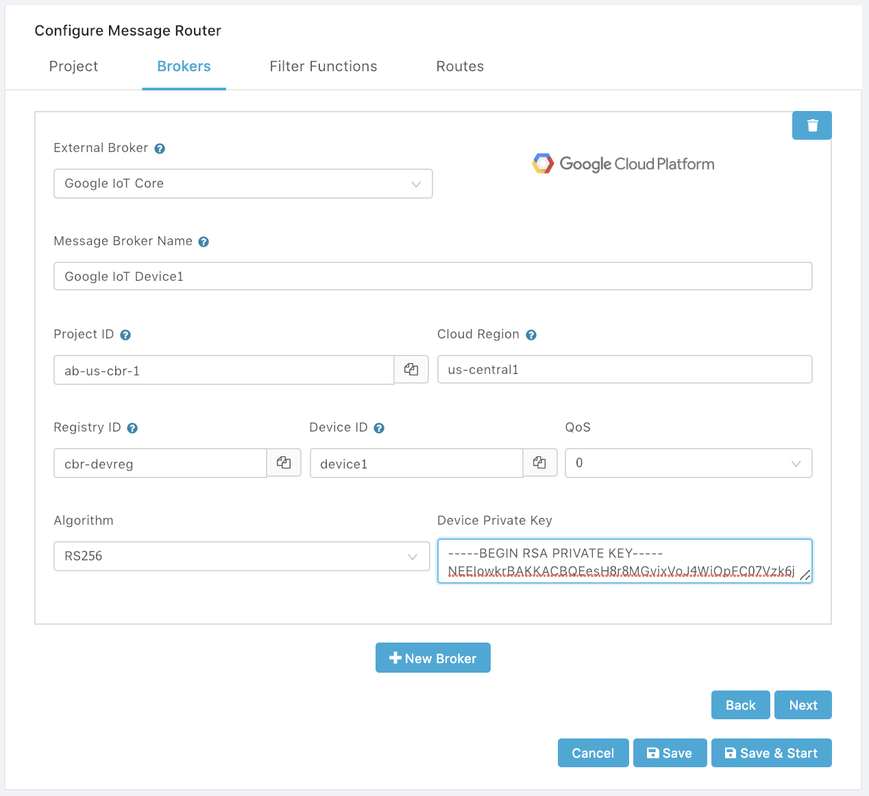
- Click Add Broker to configure another broker, or click Next to configure any data filter functions.
Connecting to the IBM Watson IoT Platform
Connecting a device to Watson IoT Platform involves registering the device with Watson IoT Platform and then using the registration information to configure the device to connect to Watson IoT Platform. Edge One™ connects to Watson IoT using TLS transport over MQTT.
-
Configure the MQTT device connection that will be used to connect to Watson IoT. The instructions to create and register a device can be found in the Connecting Devices section of the Watson IoT Platform documentation.
-
Select “IBM Watson IoT” from the External Message Broker dropdown menu.
-
Enter a name for the message broker.
-
Enter the Organization ID that was configured for the device. It is string ID of the IBM cloud project that owns the registry and device.
-
Enter the Device Type of the device registry, for example, my_device_type.
-
Enter the Device ID. The device ID is used to identify the device in the Watson IoT Platform dashboard and is also a required parameter for connecting your device to Watson IoT Platform. For example, my_first_device.
-
Enter the Authorization Token provided by Watson IoT when the device is registered and the Authentication type is token. It is a required parameter to connect to Watson IoT.
-
Select the QoS level for the MQTT connection.
Here is a sample configuration for an Edge One™ Google IoT Core Message Router device.
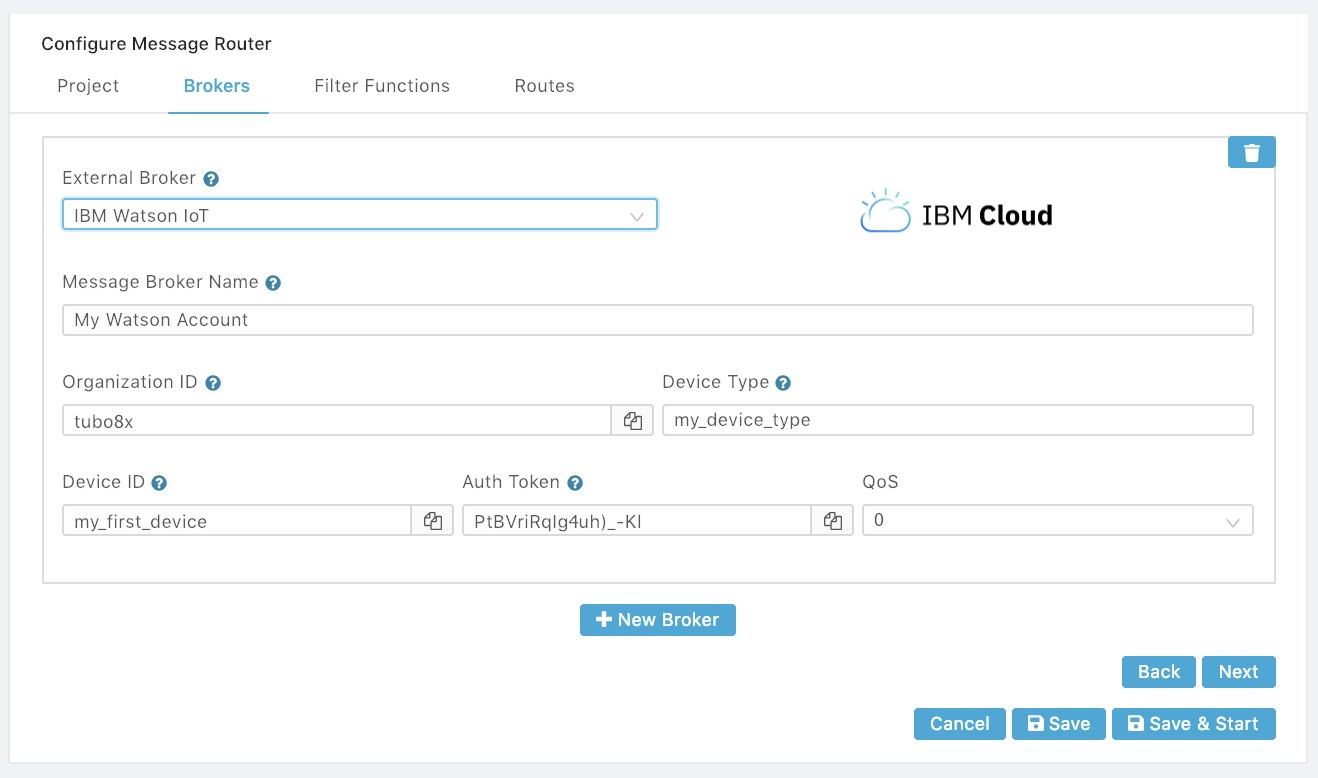
- Click Add Broker to configure another broker, or click Next to configure any data filter functions.
Configuring Connectivity to an Apache Kafka Broker
The Message Broker allows the connection of Edge One™ as a Kafka producer. The configuration of the connection requires that you understand how the Kafka broker is configured to accept connections and whether authentication is required or not.
To configure a Kafka connection:
- Configure the Kafka broker.
- Select “Kafka” fron the External Message Broker dropdown menu.
- Enter a name for the message broker.
- Enter the IP Address of the Kafka broker host.
- Enter the Port number to be used. Default is 9092.
- Select the Authentication Mode. Two modes are supported: None and SASL Plain. If None is selected got to step 7. If SASL Plain is selected:
- Enter the required User name and Password.
- If The SSL setup requires further authentication, the following options are available:
- Configure the SSL Reject Unauthorized switch. If enable, the message router will reject any connection that is not authorized with the list of available Certification Authorities.
- Enter a Certificate passphrase.
- Enter the required Private Key.
- Enter the required Certificate.
- Enter the Certificate Authority used for the authentication.
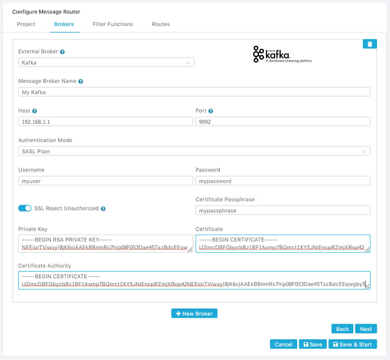
- Click Add Broker to configure another broker, or click Next to configure any data filter functions.
Configuring Data Filter Functions
The Message Broker allows to program one or more custom functions in JavaScript to filter, modify or process the data before sending it to the destination.
These functions become available to use when configuring routes.
Here are some examples:
- A function to drop the message received and send a null value.
function dropMsg(msg){
	return null;
}
- A function to inject a field x with value hello into the message.
function injectVar(msg){
   msg.x = "hello"; return msg;
}
- A function to add dynamic topics.
function changeTopic(msg) {
  let i = Math.floor(Math.random()*10); // random number
  msg.topic = 'hello/' + i;
  return msg;
}
- A function to split a message into multiple messages. For example, if the data message is a JSON object with multiple fields and you want each field to be published into its own topic in the target IoT platform, you can use this function.
function split(msg) {
  // split a message in multiple messages
  return msg.vals.map((rec) => {
    return {
      topic: 'output/' + rec.k, // custom channel
      value: rec.v
    }
  })
}
- A function to flatten the data received from the source protocol or project into simpler objects.
function flatten(msg){
   msg.data = msg.vals || 'No vals';
   delete msg.vals;
   return msg;
}
- A function to mediate data between a source Modbus connector and an OPC UA destination. The example below maps Modbus register addresses 100 and 200 with OPC UA nodes opcTagX[1] and opcTagY[0];opcTagY[1] of OPC UA Group 0, respectively.
function modbusTopOPC(msg) {
  let MAP = {
    '100': 'opcTagX[1]',
    '200': 'opcTagY[0];opcTagY[1]'
  };

  return {
    g: 0, // target group 0
    vals: msg.vals.map((reg) => {
      return {
        k: MAP[reg.k],
        v: reg.v,
      };
    })
  };
}
Clicking Next after configuring the optional functions, opens the Routes tab to configure data sources and destinations for the Message Router.
Configuring Routes
The Routes tab allows the configuration of one or more message routes with or without data filtering. A source can have multiple destinations, and multiple sources can have different or shared destinations. Configuring a route requires a few simple steps:
-
Open the Routes tab.
-
Click on the edit icon ( ) of the default sample route or click on New Route button to open the Edit Routes tab.
-
Set the Enabled switch to ON to enable the route. This switch can also be used to disable the selected route.
-
Set the Store and Forward switch to ON to enable Store and Forward on this route.
-
Select the Source IoT Broker.
- The list of available MQTT message brokers includes all the brokers configured in the Brokers tab, as well as the Edge One™ Internal Message Broker. The selection affects what is shown as available data sources.
- If the selection is an External Message Broker such as CloudPlugs IoT, AWS IoT, Google IoT Core, etc., you will be able to input a data source channel or topic.
- If the selection is the Edge One™ Internal Message Broker, you will be able to:
- Select an existing project as data source. The Project must be running for it to produce data, or
- Use a custom channel/topic to read data from the Internal Message Broker.
-
Select or Enter a data source channel or project.
-
Optionally, select one or more available Data Filters.
-
Enable Load Balancing when there are multiple destinations and the data should be sentin a round robin fashion. For example, if there are 3 destinations, the first message will be sent to the first destination, the second to the second, the third to the third, the fourth to the first destination, etc. If Load Balancing is Disabled (default), and there are multiple destinations, all the messages will be sent to the first available destination.
-
Select the Destination IoT Broker.. Much like the source, the destination can be any configured External Broler or the Edge One™ Internal Broker.
-
Select the Destination channel/topic or Project.
- If the destination IoT Broker is an External Message Broker, you can set a target data channel/topic.
- If the destination IoT Broker is an Internal Message Broker, you can either:
- Select a project that is running or will be running when the Message Router is running.
- Enter a target channel or topic on the Edge One™ Message Broker. If no destination channel is specified (see example below), the default destination channel/topic is either data/project_id/group_id or the channel/topic used by the Internal Broker to receive data.
- If required, Add another destination. See the example configuration below.
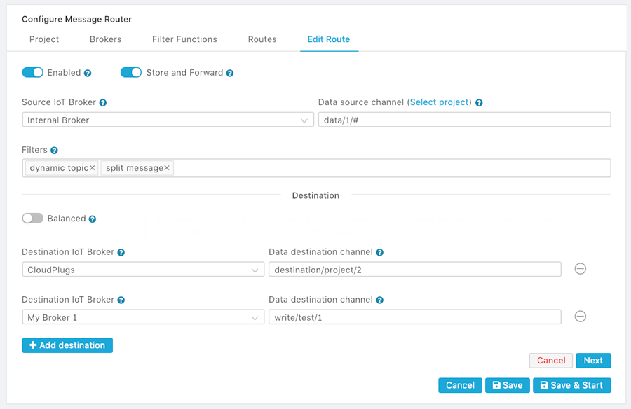
- When the route is fully configured click Next. The routes table will be updated and will display the routes configured.
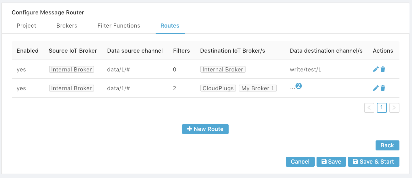
- Save or Save & Restart the Message Router.
WARNING!
Make sure the Message Router is running when your projects are running. Otherwise, no data will be sent to the cloud.