3. Configuration
OPC UA Client Overview
This guide describes how to configure and use an Edge One™ OPC UA Client. The OPC Unified Architecture (UA), released in 2008, is a platform independent service-oriented architecture that integrates all the functionality of the individual OPC Classic specifications into one extensible framework.
This multi-layered approach accomplishes the original design specification goals of:
- Functional equivalence: all COM OPC Classic specifications are mapped to UA
- Platform independence: from an embedded micro-controller to cloud-based infrastructure
- Secure: encryption, authentication, and auditing
- Extensible: ability to add new features without affecting existing applications
- Comprehensive information modeling: for defining complex information
This guide describes how to configure the Edge One™ OPC UA Client module and it includes the following sections.
- Requirements for installation of the OPC UA Client.
- Creating the OPC UA Client indicates the steps for creating the OPC UA Client project.
- Configuring the Project indicates the initial steps for configuring the OPC UA Client project.
- Configuring the Server Access describes how to configure the access to an OPC UA Server.
- Configuring Data & Event Exchange Methods describes the options to configure data and event information exchange with the OPC UA Server.
- Configuring Groups indicates how to configure OPC UA Groups.
- Selecting Nodes for the Client indicates on how to select the Nodes to use on the Client.
- Managing Nodes describes how to manage Nodes on the Client.
- Importing nodes describes how to import Nodes from a CSV file.
- Exporting nodes describes how to export Nodes on a CSV file.
- Viewing Node Real Time Data
Once the project is configured and Saved you must create a Message Router project and configure the cloud access parameters to connect uni-directionally or bi-directionally to CloudPlugs or a supported IoT cloud service.
Requirements
Here are the first few things you need to find out to configure the Edge One™ OPC UA module:
- IP Address of the OPC UA Server, or of the OPC UA Local Discovery Service (LDS) host.
- TCP Port used by the OPC UA Server, or by the Local Discovery Service (LDS) host.
- Directory path to the OPC UA Server, or to the LDS host.
- Authentication type used by the OPC UA or LDS Server.
- Credentials and certificates used by the OPC UA or LDS Server.
Creating an OPC UA Project
The following steps are required to connect and configure OPC UA devices on the Edge One™ platform.
- Login to the Edge One™ platform.
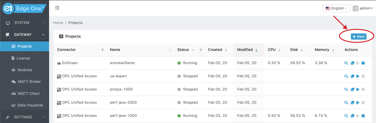
- Select “Gateway” then Projects on the left panel navigation bar.
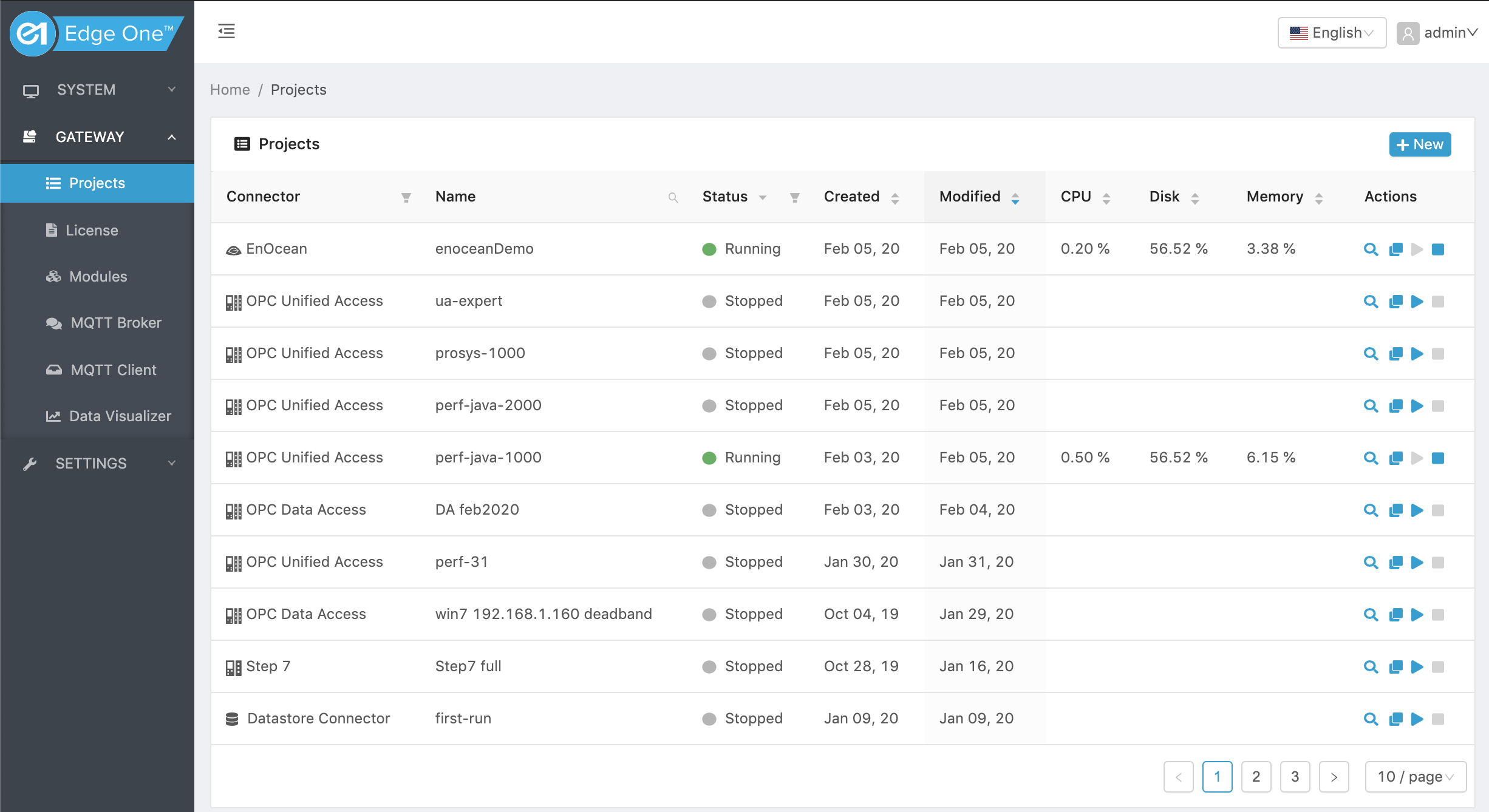
- Click ( ) on the Projects title bar to create a new project.
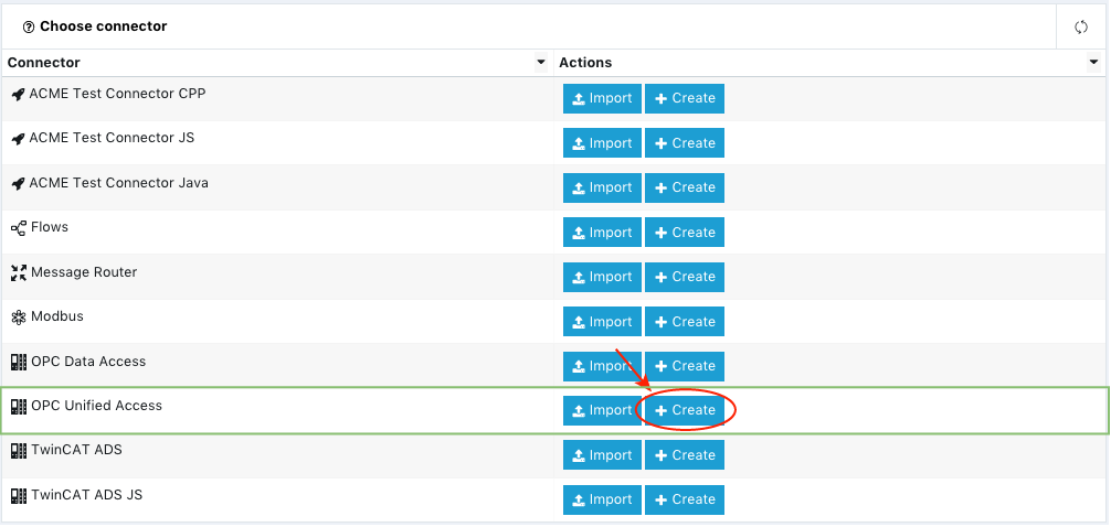
- Click on New on the OPC UA module row.
- Configure your OPC UA Client.
Configuring the OPC UA Client Project
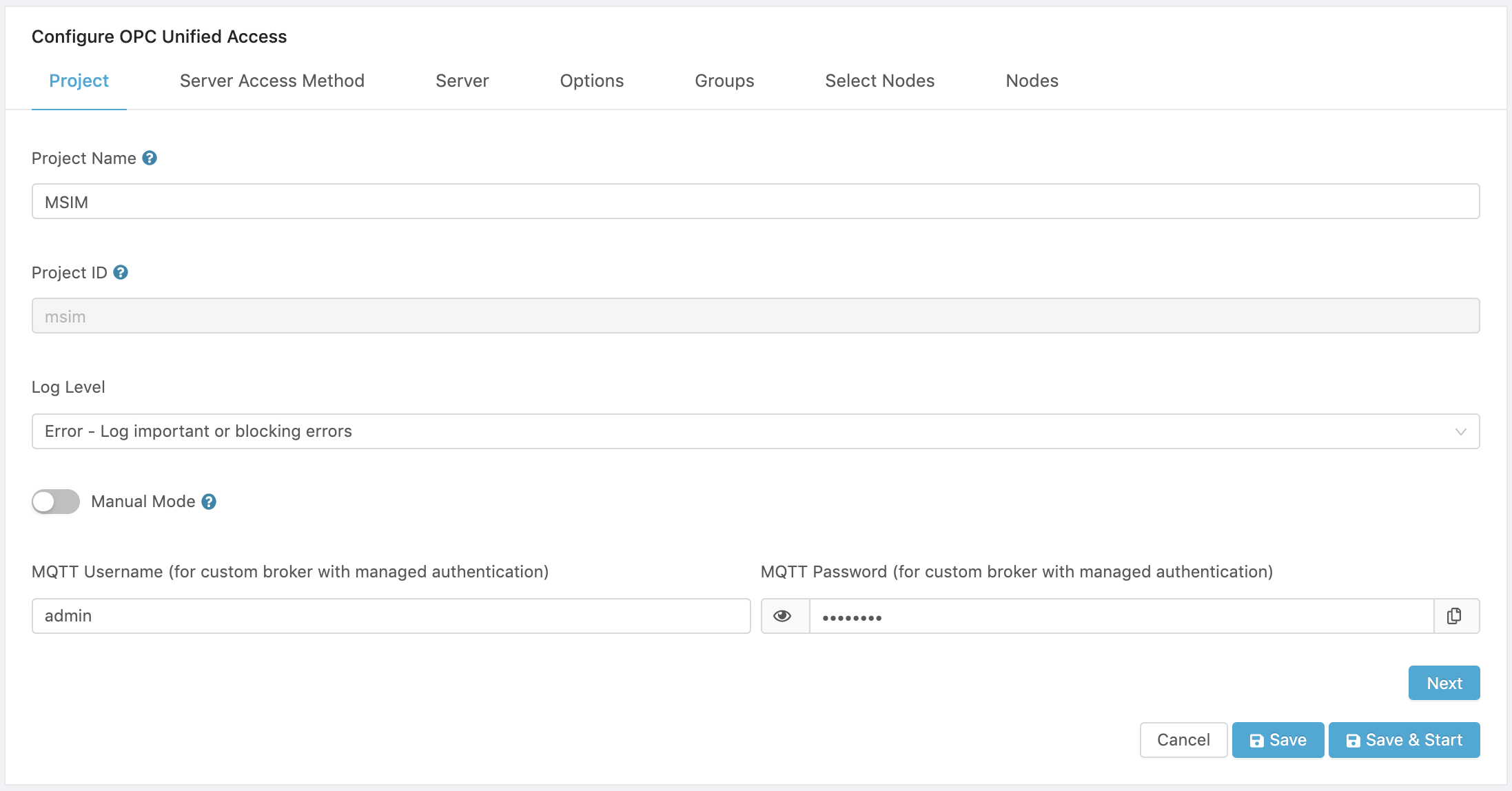
- In the Project tab:
- Enter a Project Name for the project.
- Enter a Project ID for the project. This ID is used to identify the root topic to which data will be written by the project. It is recommended to keep the Project ID (pid) short. It can be a number (e.g., 11), or an alphanumeric string of 16 characters or less with no blank spaces (e.g., opcua-server1). If not pid is entered, the project name is used as default.
- Selet the log level. Default is Warning which logs non-blocking events and errors.
- Select whether or not the project will be started automatically when the OPC UA Client module container is started. To start the project manually using the web interface, set the Manual mode switch to ON.
- If an external or custom MQTT broker configured through the Settings->Server interface will be used, enter the broker’s access credentials.
- *Click on Next to open the Server tab.
Configuring the OPC UA Server Access
In the Server Access Method tab:
- Select the Server Configuration:
- Manual which allows to enter manually the access information of a specific OPC UA Server.
- Local/Global Discovery Server which allows to enter the network and security credentials of a Discovery Server which can provide a list of available OPC UA Servers.
- If Manual is selected, click Next to configure the server.
- If Local/Global Discovery Server is selected, the page will expand to allow you to enter the LDS Configuration parameters.
The following subsections explain how to use each option.
Configuring the OPC UA Server Manually
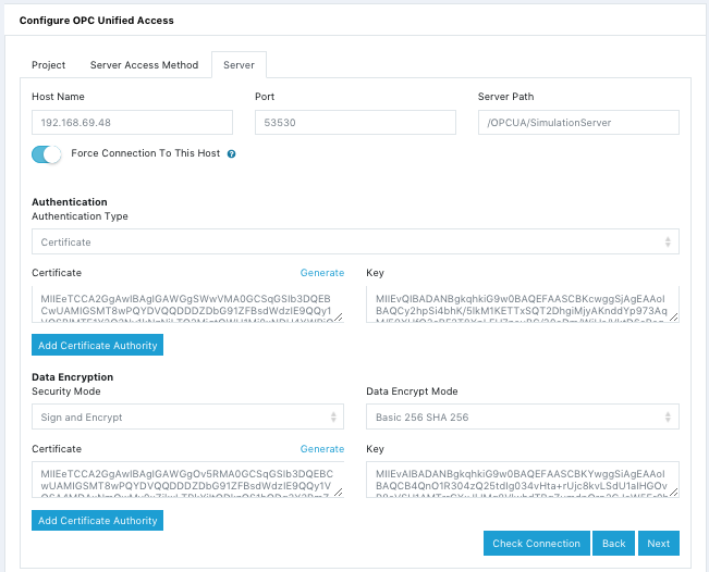
If you want to connect to a specific Server and know its access information, follow the instructions below:
- Enter the Host Name or IP Address of the OPC UA Server host.
- Enter the TCP Port of the OPC UA Server or use the default port 53530.
- Enter the directory path for the OPC UA Server.
- You can set the switch to Force connection to this host when the Edge One™ hosting the Client and the OPC UA server do not share the same DNS.
- Select the Authentication Type:
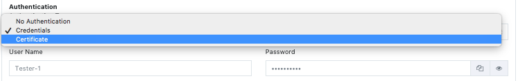
- No Authentication is used when the Server is open and requires no authentication.
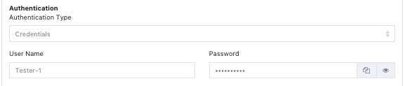
- Credentials: requires to enter a User name and Password.
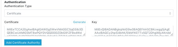
- Certificate: requires to add:
- A Certificate
- A Key
- Optionally, a Certificate Authority.
You can use the Generate button to have the system automatically generate the Certificate and Key that will be accepted by the Server.
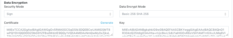
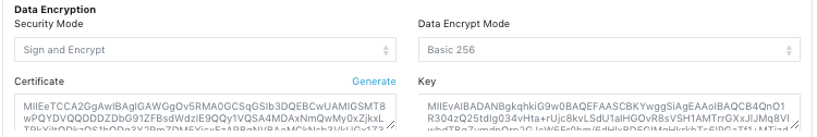
- Select the Security Mode:
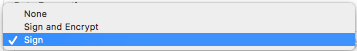
- None is used when the Server has an open connection without encryption.
- Sign is used to add a signature with no encryption. You can use the Generate button to have the system automatically generate the Certificate and Key that will be accepted by the Server.
- Sign and Encrypt add a signature and encryption. You can use the Generate button to have the system automatically generate the Certificate and Key that will be
accepted by the Server. Supported encryption modes include:
- Basic 256.
- Basic 128 RSA 15.
- Basic 256 SHA 256.
- Click on Check Connection to verify that the parameters match the server connection requirements.
- If the connection is successful continue on 10 below. Otherwise, verify all your parameters.
- Click Next to configure the Data Exchange Options with the server.
Here is a sample OPC UA Server configuration:
Using an LDS Server to configure the OPC UA Server Access
You can also use an LDS server to configure the access to an OPC UA Server.
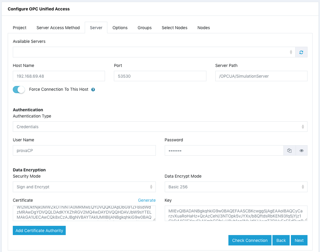
To set the configuration parameters for the LDS Server, select Local/Global Discovery Server in the Server Access Method tab, and follow the instructions below:
- Enter the Host Name or IP Address of the LDS Server host.
- Enter the TCP Port of the LDS Server or use the default port 53530.
- Enter the directory path for the LDS Server.
- You can set the switch to Force connection to a host when the Edge One™ hosting the Client and the LDS server do not share the same DNS.
- Select the Authentication Type:
- No Authentication is used when the Server is open and requires no authentication.
- Credentials: requires to enter a User name and Password.
- Certificate: requires to add:
- A Certificate
- A Key
- Optionally, a Certificate Authority.
* **No Authentication** is used when the Server is open and requires no authentication.
* **Credentials:** requires to enter a **User name** and **Password.**
You can use the Generate button to have the system automatically generate the Certificate and Key that will be accepted by the Server.
- Select the Security Mode:
- None is used when the Server has an open connection without encryption.
- Sign is used to add a signature with no encryption. You can use the Generate button to have the system automatically generate the Certificate and Key that will be accepted by the Server.
- Sign and Encrypt add a signature and encryption. You can use the Generate button to have the system automatically generate the Certificate and Key that will be
accepted by the Server. Supported encryption modes include:
- Basic 256.
- Basic 128 RSA 15.
- Basic 256 SHA 256.
- Click on Discover Servers to open the Server tab and see a dropdown menu with the list of available servers.
- Select a Server from the list.
- Verify the connectivity to the Server by clicking on Check Connection.
- If the connection is successful continue on step 11 below. Otherwise, verify that the selected Server is still available.
- Click Next to configure the Data Exchange Options with the server.
Here is a sample OPC UA Server configuration resulting from the use of an LDS server:
Data and Event Exchange Options with the OPC UA Server
The Options tab allows to configure data and event exchange options between the OPC UA Client and its OPC UA server(s), as well as data filters and triggers.
These configuration settings become the default for all Groups that belong to this project. However, each Group may then be configured individually with specific options. For example, you may have a Group that reads changes in data values and another one that only reads events.
Data and Event Configuration
The available configuration options for data and event exchange with the OPC UA server include:
- Subscribe to changes in data value. This option allows the client to only get data when the value of a Node changes in the Server, and it provides a very efficient method to read data from the Server.
- Subscribe to all data values with a sampling rate. The Client will get all the data values from the Nodes selected from the Server with a specified Sampling period in milliseconds.
- Subscribe only to events. The Client will only get event information from the server.
- Write MQTT data to server without a subscription. The Client will only write data read from an MQTT topic set up with the the Edge One™ Message Router to the Server.
For Data subscriptions, the following options are also available:
Queue Size
This parameter allows to configure the maximum number of data points to be held in the queue of the OPC UA Client, as well as the policy for discarding messages when the queue is full and data keeps on filling it up.
The default queue size is 10.
When the Discard oldest switch is on, the oldest data points will be discarded when the queue is full using a FIFO (First In, First Out) model. When the switch is not set, the most recent data values will be replaced with the new data.
Deadband Filters
OPC UA Clients may read or write DataItems, or monitor them for value changes. The Services needed for these operations are specified in Part 4. Changes are defined as a change in status (quality) or a change in value that exceeds a client-defined range called a Deadband. To detect the value change, the difference between the current value and the last reported value is compared to the Deadband.
In OPC UA, the DataChangeFilter defines the conditions under which a DataChange Notification should be reported and, optionally, a range or band for value changes where no DataChange Notification is generated. This range is called Deadband. Deadband specifies a permitted range for value changes that will not trigger a data change Notification. Therefore, Deadband filters provide a method to exclude less significant data records. Deadband can be applied as a filter when subscribing to Variables and is used to keep noisy signals from updating the Client unnecessarily, saving traffic and compute resources. The DataChangeFilter contains a deadbandValue which can be of type AbsoluteDeadband or PercentDeadband. For more details, consult Part 4 of the OPC UA Specification.
The Deadband is applied only if:
- the trigger includes value changes and
- the deadbandType is set appropriately.
The following deadbandTypes are supported by the OPC UA Client:
- None which is the default does not apply any filters to data.
- Absolute. For this type, the deadbandValue contains the absolute change in a data value that shall cause a Notification to be generated. This parameter applies only to Variables with any Number data type.
An exception that causes a DataChange Notification based on an AbsoluteDeadband is determined as follows:
Generate a Notification if (absolute value of (last cached value - current value) > AbsoluteDeadband)
The last cached value is defined as the last value pushed to the queue. If the item is an array of values, the entire array is returned if any array element exceeds the AbsoluteDeadband, or the size or dimension of the array changes.
The valid range for Deadband Value is 0 to 9,999,999,999. The default is 0.
For example: If the Type is Absolute and the Deadband Value is set to 10, and the last value was 20, only values equal to 30 and higher, or 10 and lower will be allowed by the OPC UA Client.
- Percent. For this type of Deadband the deadbandValue is defined as the percentage of the EURange. That is, it applies only to AnalogItems with an EURange Property that defines the typical value range for the item. This range shall be multiplied with the deadbandValue and then compared to the actual value change to determine the need for a data change notification. The following pseudo code shows how the deadband is calculated:
DataChange if (absolute value of (last cached value - current value) > (deadbandValue/100.0) * ((high–low) of EURange)))
The range of the deadbandValue is from 0.0 to 100.0 Percent. Specifying a deadbandValue outside of this range will be rejected and reported with the StatusCode Bad_DeadbandFilterInvalid.
If the Value of the MonitoredItem is an array, then the deadband calculation logic shall be applied to each element of the array. If an element that requires a DataChange is found, then no further deadband checking is necessary and the entire array is returned.
For example:   If the Percent value is set to 20, and the maximum and minimum values for the node are 1,000 and -100, respectively, the server will only send data
when the changes in data value exceed (1000 - (-100) = 1,100 x 20% = 220).  If the last value was 100, only values greater than 320 and less than -120 will be sent to
the Client.
Data Change Triggers
The OPC UA Client supports the programming of triggers which cause the Server to send a Notification to the Client. Notifications are on by default and they are expressed as the Server publishing data or an event. There are three types of triggers that can be configured based on changes in data values:
- Status or Value or TimeStamp. The notification will be sent to the Client when the Status, or the Value or the Source TimeStamp of the data changes. This is the default trigger.
- Status or Value. The notification will be sent to the Client when the Status or the Value of the data changes.
- Status. The notification will be sent to the Client when the Status Code of the data changes.
Once all the Options have been configured for the Client, Click Next to configure the Client Node Groups.
Note that OPC UA triggers are different than the CloudPlugs IoT triggers or those that can be configured using Edge One™ Flows. Applications may be written by the user to configure actions based on data or events received from the OPC UA server using either CloudPlugs IoT triggers or actions programmed using Edge One™ Flows.
Configure a Group
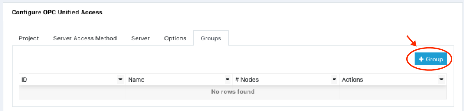
To configure a Group of Nodes, open the Groups tab.
- Click on the Add Group button.
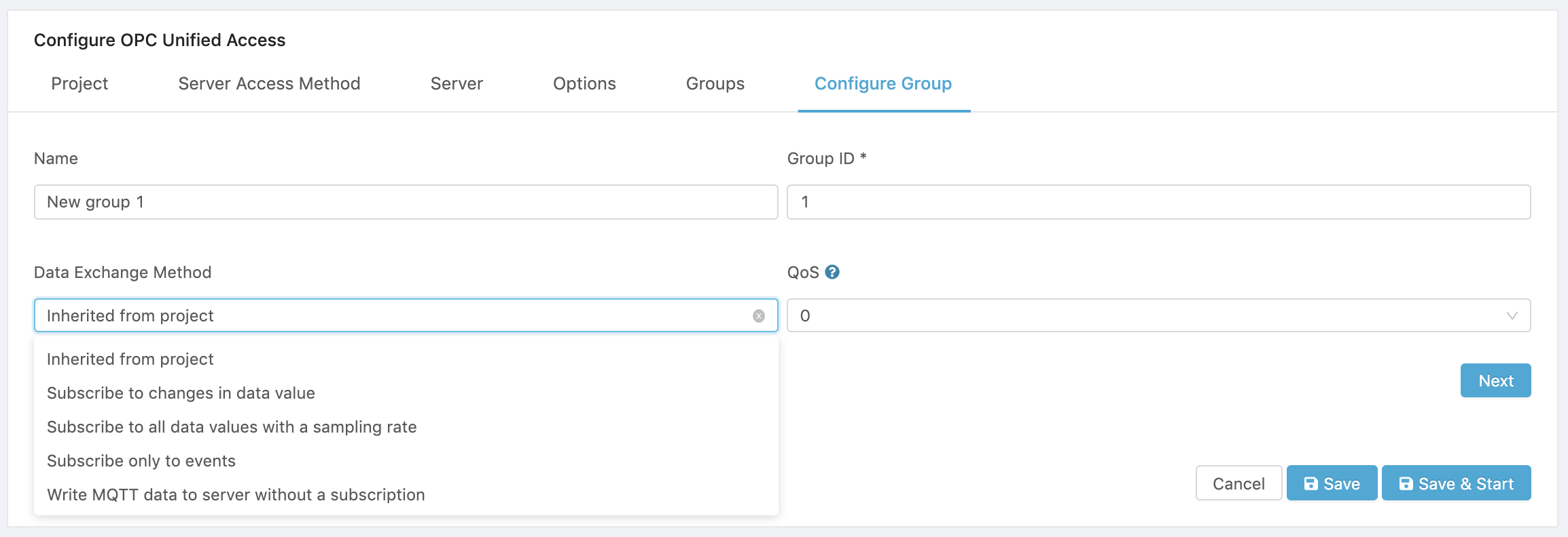
- Enter the Group Name which is a reference name to easily identify the Group.
- Enter the Group ID. This is a required parameter which is used to identify the Group in an MQTT topic or channel. The Group’s Node data is published into MQTT topics, or CloudPlugs channels with the structure Project-ID/Group-ID.
- Select the Data Exchange Method.. There are 4 options:
- Inherited from project. Uses the method set up for the Project under Options.
- Subscribe to changes in data values. This option allows the Group of Nodes to only get data when the value of a Node changes in the Server, and it provides a very efficient method to read data from the Server.
- Subscribe to all data values with a sampling rate. The Group will get all the data values from the Nodes selected from the Server with a specified Sampling period in milliseconds.
- Subscribe only to events. The Group will only get events from the Server.
- Write MQTT data to server without a subscription. The Group will only write data read from an MQTT topic set up with the the Edge One™ Message Router to the Server.
- Select a quality of service (QoS) level. This parameter determines the QoS that will be used by the connector to publish messages on the MQTT broker used by your Edge One™ project. The default is QoS 0.
- QoS 0 - at most once is the minimal QoS. This service level guarantees a best-effort delivery. There is no guarantee of delivery.The recipient does not acknowledge receipt of the message and the message is not stored and re-transmitted by the sender. QoS level 0 is often called “fire and forget” and provides the same guarantee as the underlying TCP protocol. Use this level when you require high-throughput and losing messages is not critical.
- QoS 1 - at least once. This service level guarantees that a message is delivered at least one time to the receiver. The sender stores the message until it gets a PUBACK packet from the receiver that acknowledges receipt of the message. It is possible for a message to be sent or delivered multiple times. Use this method when you need a guarantee that the messages are all delivered. The setting sacrifices performance for reliable message delivery.
- Click Next to complete the Group creation process and to open the Groups tab.
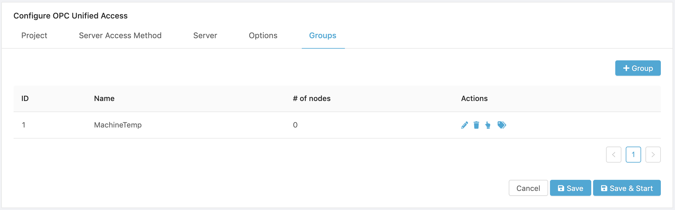
- The Groups tab displays the Groups created and allows to select and manage the Group’s Nodes.
Configure the Group’s Nodes
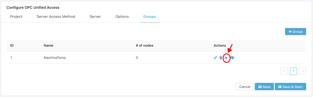
To configure a Group’s Nodes, open the Groups tab.
- Click on the Select Nodes ( ) icon.
- There are two options to add nodes to a Group:
- Load and Select Nodes.
Load Nodesreads the available Nodes from the OPC Server. If loading is taking a long time, the Server may have a large number of nodes, or it may be unresponsive, and the operation will eventually timeout. - Import Nodes. Allows the import of valid Nodes from a CSV file.
- Load and Select Nodes.
In this section, we focus on loading and selecting Nodes. To do this:
-
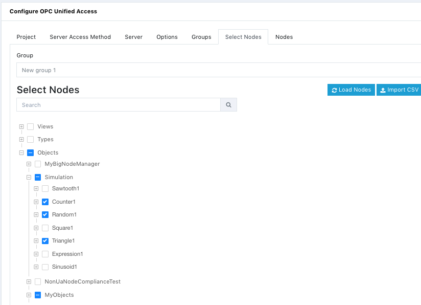
Click on Load Nodes. The Nodes that are loaded from a Server are displayed on a tree that allows individual node or branch selections. Nodes that are imported on a CSV file are displayed as XXXX
-
Select the individual Nodes or Node Branches required by your application by clicking on the Selection boxes. You can Search for Nodes using the Search toolbar. Selected Nodes can be Unselected by clicking on them again.
Below is a Node selection example.
- There is no additional button such as Select or Next to press. All the selected nodes will be visible in the Nodes tab.
- Save or Save and Start your Project since it is now configured to run.
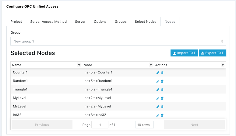
Nodes
The Nodes tab displays the Nodes selected and allows both edit ( ) and delete ( ) operations on the Nodes.
When a Node is edited or deleted you must Save and Start for the changes to take effect.
Importing Group Nodes
You can import Group Node configurations from a Tab Delimited Text file.
WARNING!
Any existing registers will be deleted and replaced by the imported registers.
To preserve existing registers, Export them as a CSV file and add the exported data to the file to be imported.
The file must conform to the following data structure and must have a header row whose values are ignored, where <tab> is the tab character.
	Node ID<tab>Name

	Where:

		Node ID:		Schema that represents a fully qualifies Nodeid. The format of the string is:
						<namespace index> - a base 10 number
						<identifier type> - a flag with one of the following values: i (numeric), s (string), g (GUID), b (opaque Bytestring)
						<identifier> - identifier encoded as a string. It may contain any non-null UTF8 character including a whitespace.

		Name:			String. The name given to the Node.

	Example:
		\t represents a tab character.
		Node ID\tName
		ns=0;i=7692\tBuildInfo
		ns=0;i=7680\tX509IdentityToken
		ns=0;i=7749\tScalarTestType
		ns=2;s=Temperature\tFloor1 Temperature
		ns=3;g=06056e57-6c5c-322b-123f-c3a5613bd34c\tSensor23
		ns=1;b=M/SbJKsOUkeBCePcx24oCA==\tMyDevice
Only tab “\tab” separators are supported, and there can only be one tab between each field. The import function is used for multiple modules and some of the connector variables support support value strings with commas; therefore, only Tab Delimited Text files are supported.
Note that any existing nodes in the Group selected for the import will be replaced by the imported nodes.
To import a nodes configuration file:
- Open the Nodes tab.
-
Click on the [ Import TXT ] button to open the Import Nodes tab.
-
Read the Instructions and click on the [ Upload file ] button.
-
Select a valid Tab Delimited Text file and complete the upload.
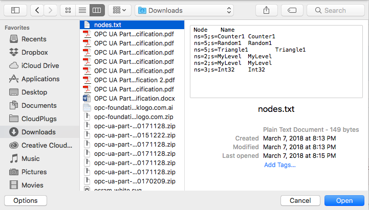
The text file has the tab delimited data shown below, and it was created with a standard text editor.
- Verify that the nodes were imported correctly by opening the Nodes tab.
- Configure the IoT cloud communications parameters by creating or configuring a Message Router project.
Exporting Group Nodes
You can export Nodes in a Tab Delimited Text file.
The file will conform to the following data structure and will have a header row, where <tab> is the tab character.
Node ID<tab>Name
Only tab “\tab” separators are supported, and there will only be one tab between each field.
To export a register configuration file:
- Open the Nodes tab.
-
Click on the [ Export TXT ] button to open the Export Nodes tab.
-
Read the Instructions and click on the ( Download file ) button.
-
Enter a name for the Tab Delimited Text file, or use the default and Click OK to initiate the download.
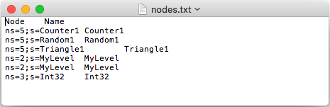
The text file has the tab delimited data shown below. It was open with a standard text editor.