6. Slave Configuration
Modbus Slave Overview
The Edge One™ Modbus Slave mode is typically used to bridge an IoT platform and new generation devices and sensors with a Supervisory Control and Data Acquisition (SCADA) or Building Management System (BMS).
The Slave receives data from the CloudPlugs IoT platform or from a supported IoT cloud service. The Slave registers are mapped into channels or topics of the IoT platform. The channels contain data in JSON format and the key/value pairs are mapped into register names and values, respectively. When the Slave or a Master writes a new value into a register, its corresponding field in the IoT platform channel is updated with the new value.
A SCADA or BMS system which acts as the Slave’s Modbus Master can read or write into the Slave’s registers thereby establishing bi-directional communications with the IoT platform and any devices connected to it.
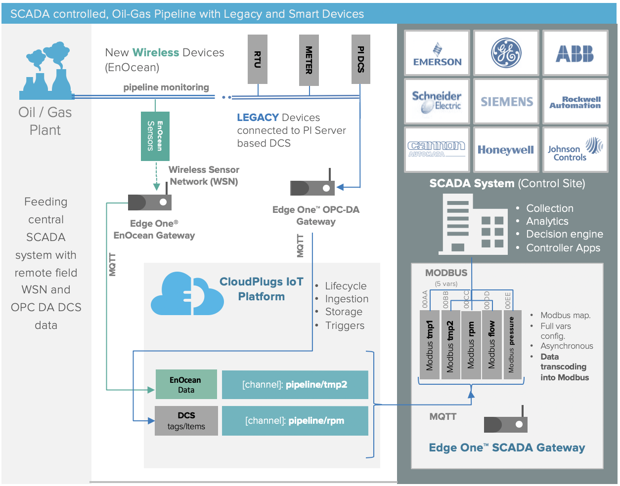
The Edge One™ Modbus Slave is, therefore, used as a gateway between an IoT platform and its devices and sensors and SCADA and BMS systems.
The image below displays such scenario for an Oil-Gas plant.
This guide describes how to configure and use Edge One™ as a Modbus TCP Slave. Currently, this is the only mode supported for Slave operations.
Modbus TCP combines a versatile, scaleable, and ubiquitous physical network (Ethernet) with a universal networking standard (TCP/IP) and a vendor-neutral data representation, providing a truly open, accessible network for exchange of process data. It is simple to implement for any device that supports TCP/IP sockets. In addition, since TCP/IP and Ethernet layers already provide checksum protection, Modbus TCP does not require a checksum calculation.
Since TCP is a connection-based protocol, it must establish a connection before transferring data. The Master (or Client in Modbus TCP) establishes a connection with the Slave (or Server). The Server waits for an incoming connection from the Client. Once a connection is established, the Server then responds to the queries from the Client until the client closes the connection.
Modbus TCP uses a big-endian representation for addresses and data items. This means that when a numerical quantity larger than a single byte is transmitted, the MOST significant byte is sent first.
By default, the Edge One™ Modbus Slave uses Port 502 as the local port, but any valid TCP port number can be used.
Modbus TCP/IP has become ubiquitous because of its openness, simplicity, low-cost development, and minimum hardware required to support it.
IMPORTANT!
Modbus Slaves (servers) are data producers. The Edge One™ Modbus module in Slave mode, must subscribe to a local or cloud IoT channel/topic and write the channel data into its registers. Therefore, the data source for the slave project must be configured in a Message Router Project.
If a Master writes one or more registers of the Slave, the corresponding channel/topic data at the local or cloud IoT source will also be updated.
The following sections describe how to configure the Edge One™ Modbus module in Slave mode.
- Requirements for installation of Modbus TCP.
- Configuring the Modbus TCP Slave describes how to add and configure the TCP Slave also called a Group.
- Configuring registers indicates how to configure the registers in a Slave or Group.
- Configuring a single register indicates on how to add and configure a single register.
- Editing a register describes how to edit a single register.
- Deleting a register shows how to delete a register.
- Adding multiple registers provides instructions on how to add and configure multiple registers with a single command.
- Importing registers describes how to import registers from a Tab Delimited Text file.
- Exporting registers describes how to export registers in a Tab Delimited Text file.
For instructions on configuring a Modbus TCP Master, please refer to its documentation.
Once the project is configured and Saved you must create a Message Router project and configure the cloud access parameters to retrieve data from CloudPlugs or a supported IoT cloud service.
Requirements
The following are the requirements to configure a Modbus TCP Slave on the Edge One™.
- The Edge One™ and the Edge One™ Modbus module need to be installed on the gateway or virtual machine acting as the Modbus Master.
- Ethernet communications between Edge One™ and the Modbus Master(s).
- Modbus TCP requires that you know or define:
- The slave ID (unit number, unit ID). While not required by the Modbus protocol since the IP address is the Slave’s address, Edge One™ requires this number to be set to identify the Slave inside an IoT channel/topic structure.
- The IP address of the Slave.
- The TCP port of the Slave.
A mis-match in any of these will result in no communication.
- Configuration of a Message Router project and route for the Slave to read data from CloudPlugs IoT channels.
Configuring a Modbus TCP Slave
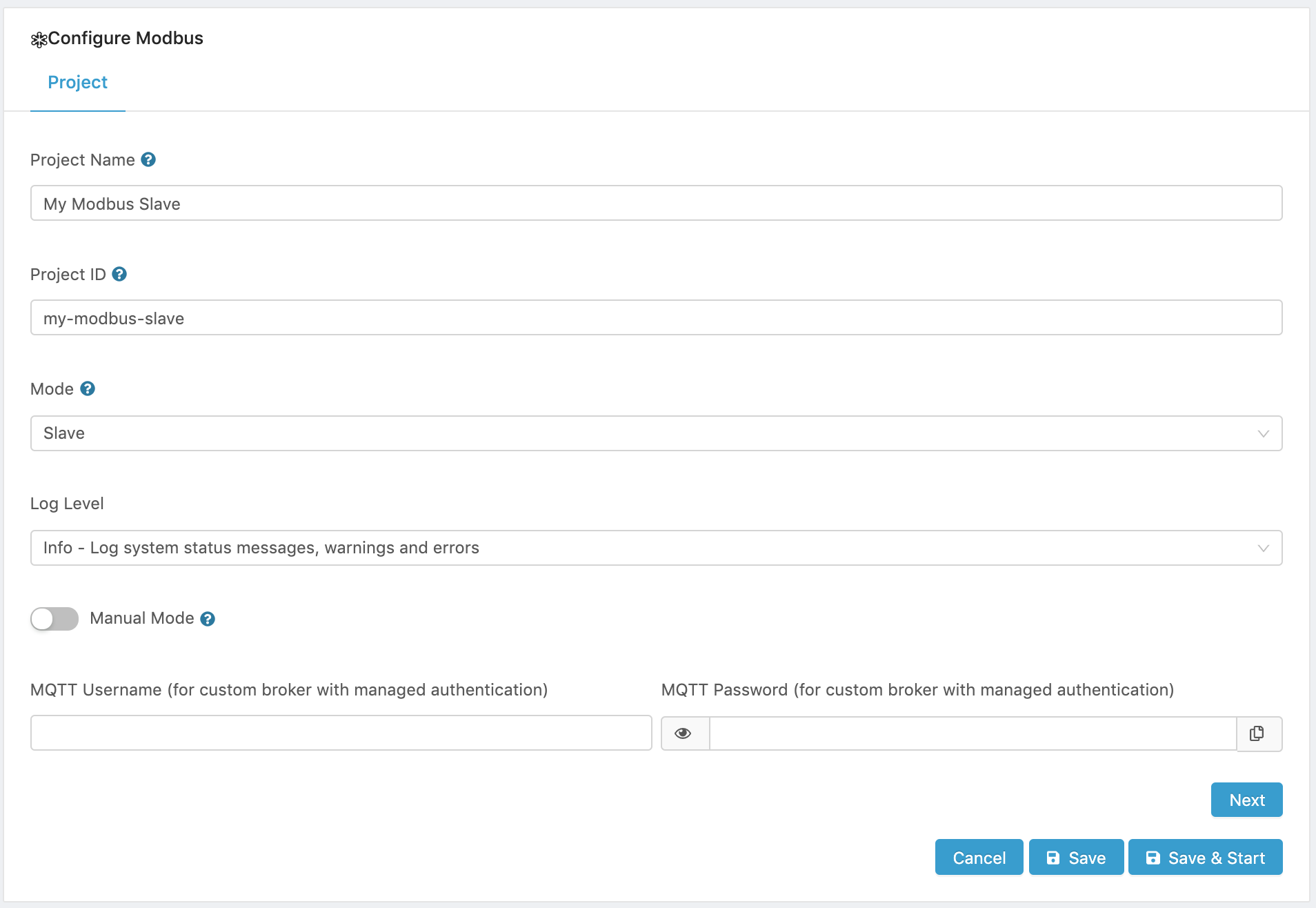
- In the Project tab:
- Enter a name for the project.
- Select Slave from the Mode dropdown menu.
- Set the log level.
- Silent - No logs will be printed on the console.
- Error - Reports only important and blocking errors that can cause malfunctions.
- Warning - All warnings for abnormal, non-blocking events as well as Errors will be reported in the logs.
- Info - All messages relevant to the current system status as well as Warnings and Errors will be reported in the logs.
- Debug - Full verbose mode. All errors, warnings, and information will be reported on the log console.
- Select whether or not the project will be started automatically when the Modbus module container is started. To start the project manually using the web interface, set the Manual mode switch to ON.
- Click on Next to open the Slave Configuration tab.
- In the Slave Configuration tab:
- Enter a Slave ID.. A Slave ID is a unique unit address from 1 to 247. As stated in Requirements, Edge One™ requires a Slave ID to build the channel/topic names to communicate with local or cloud IoT servers, from which it gets data that gets written into its registers.
- Enter the IP address of the Slave. An IP Address of 0.0.0.0 makes the Slave visible on all network interfaces enabled on the host running the Edge One™ Platform. For example, if the host has 2 network interfaces with different IP addresses, the Slave will be visible on both interfaces using the IP addresses configured by the host for those interfaces.
- Enter the Slave’s TCP Port. The most commonly used Modbus server (Slave) TCP port is 502.
- Configure the Response and Byte Timeouts, if required.
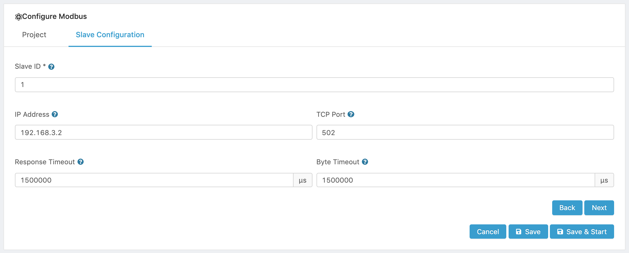
- Click Next or Save. Next will place you on the Groups tab so you can configure Groups and your registers within each Group. By default, a group called My group with Group ID 1 is created. You can edit or delete this group and add new groups.
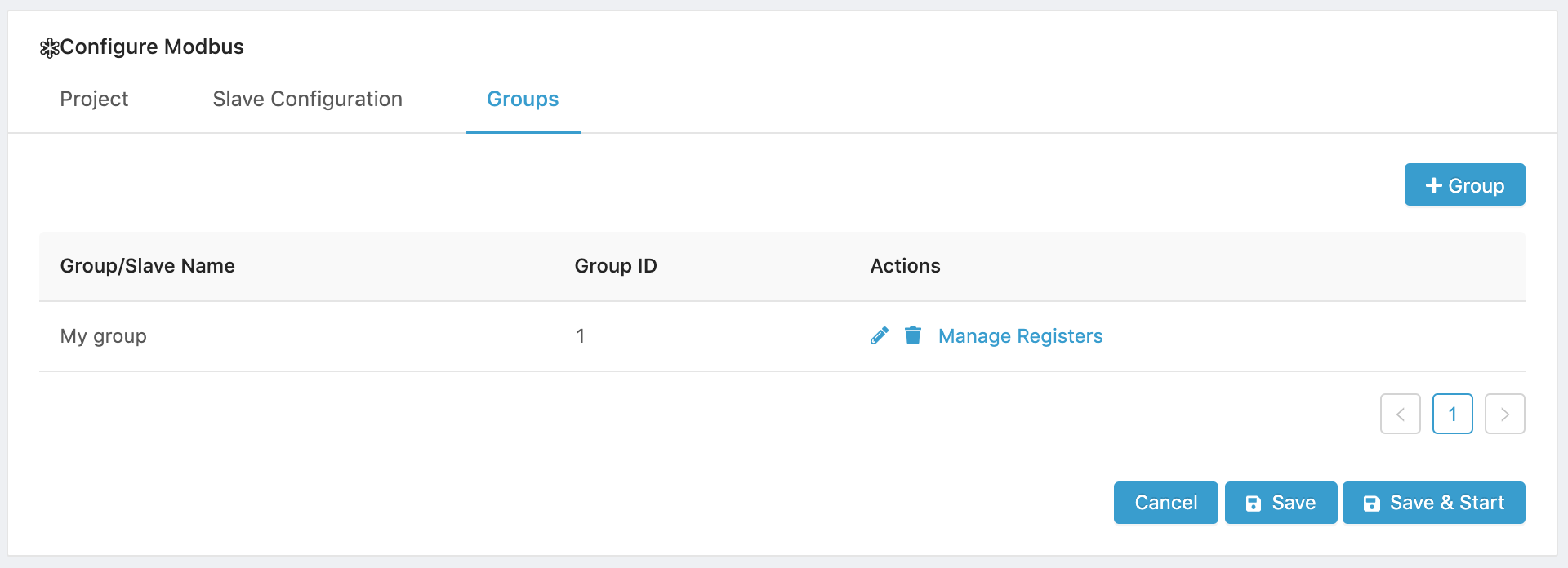
The next section describes how to configure one or multiple groups.
Configure Group(s)
After configuring the Slave parameters, the system wil automatically create a Group called My group with a default Object Type of Input Register. In this section, we will edit the default Group and will add another Group.
Please note that a Slave can have multiple Groups with each Group having a specific Object Type for all its registers.
- In the Groups tab edit the default Group by clicking on the edit icon.
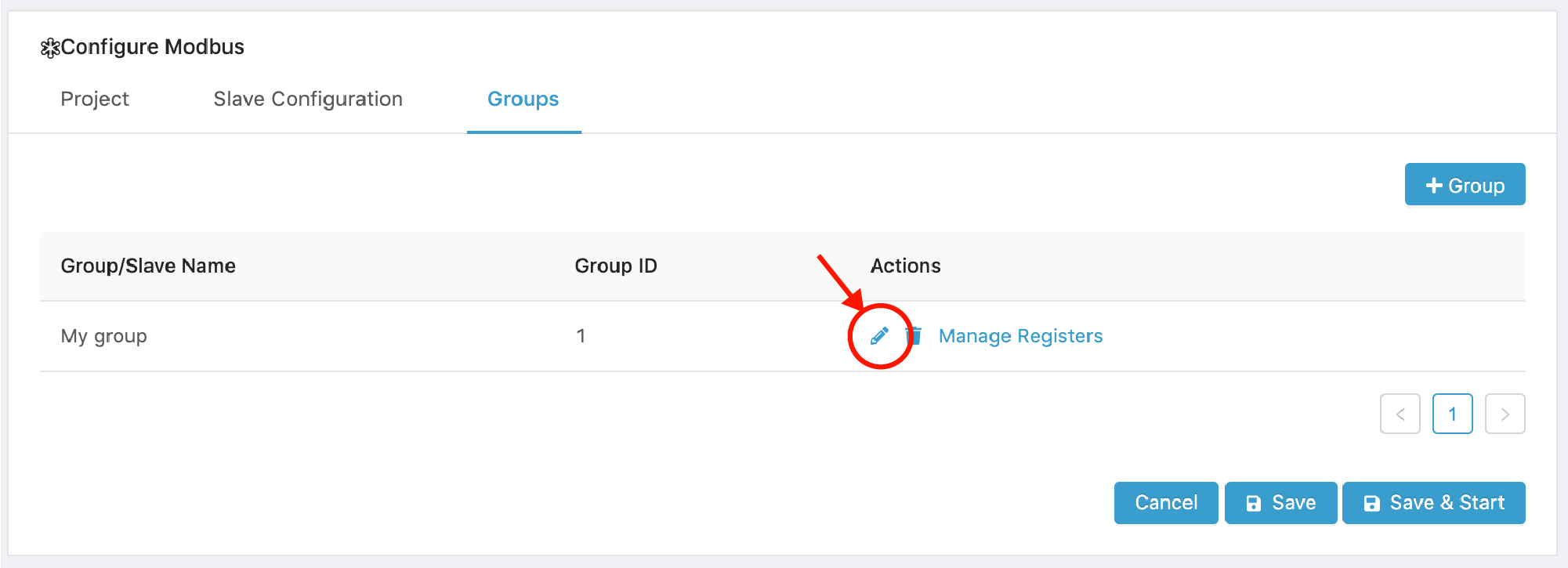
The default Group configuration opens as shown below.
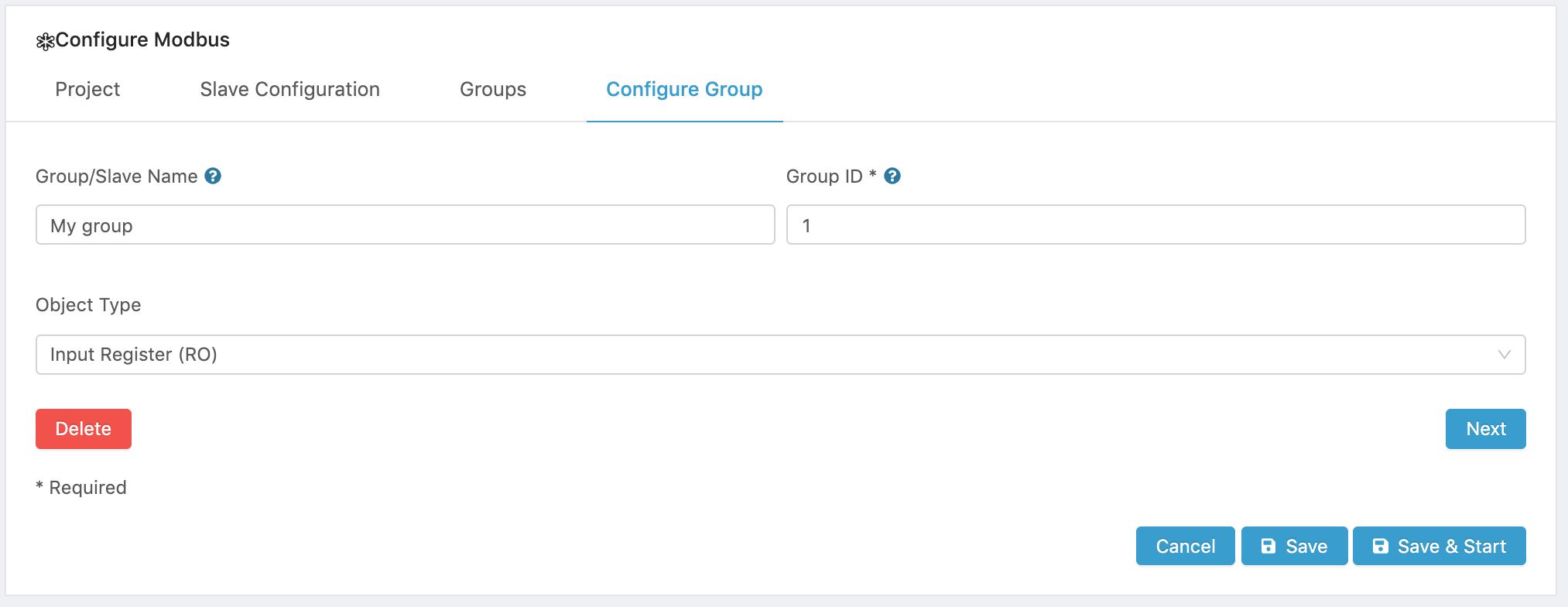
- Modify the Group’s parameters as required by your application and click Next to configure the Group’s registers or to add another Group.
- Enter a Name for the Group.
- Enter a Group ID, which is a number to identify this Group in the Edge One™ topic that will be used to read the Modbus data.
- Select the Object Type for the registers of this Group.
The following types of registers are supported:
Object Type Access Size Coil Read-write 1 bit Discrete Input Read-only 1 bit Input register Read-only 16 bits Holding register Read-write 16 bits
In the example below, we changed the Group Name to TempRegs and the Object Type to Discrete Input since we will be reading temperature values and the register will be Read Only.
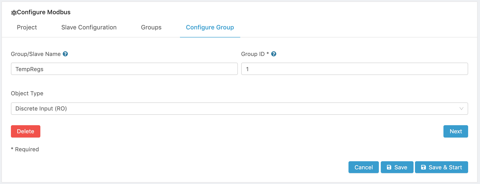
- Clicking Next returns to the Groups tab and displays the edited Group.
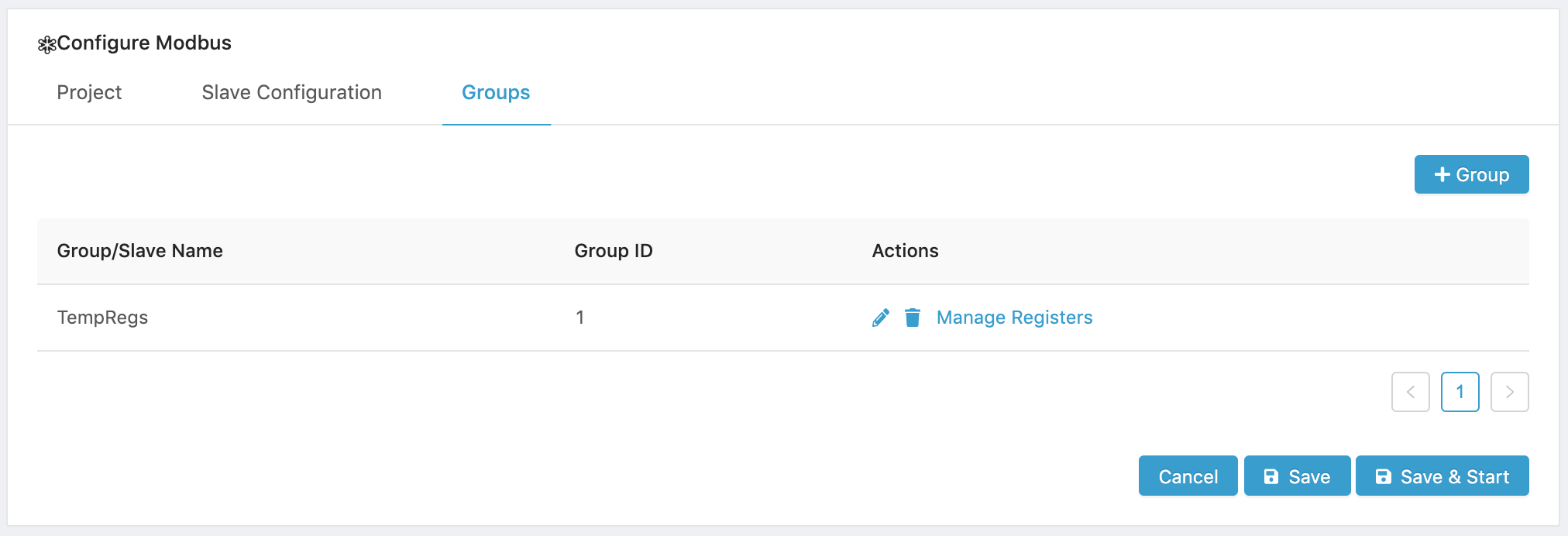
- You can add another Group with Group and configure its parameters as shown above, or you can click on Manage registers under Actions to add registers to your Group.
The next section describes how to add and configure registers.
Configure Register(s)
The registers for Slave Mode need to match the data set that will be read from the data source channel or topic. The source channel/topic holds data in JSON objects with key/value pairs.
- There are multiple ways to configure registers:
- Register allows to configure a single register.
- Multiple Registers allows to configure multiple registers at a time.
- Import TXT allows to import a Tab Delimited Text register configuration file.
- Export TXT allows to export the Slave’s registers in a Tab Delimited Text file format so it may be imported into another Slave/Group or another Modbus application.
The sections below describe each one of the register configuration methods.
- Once the registers are configured and the Project is Saved, please configure the IoT cloud communications parameters by creating or configuring a Message Router project.
To learn how to delete or edit a register, please refer to the Deleting a Register and Editing a Register sections, respectively.
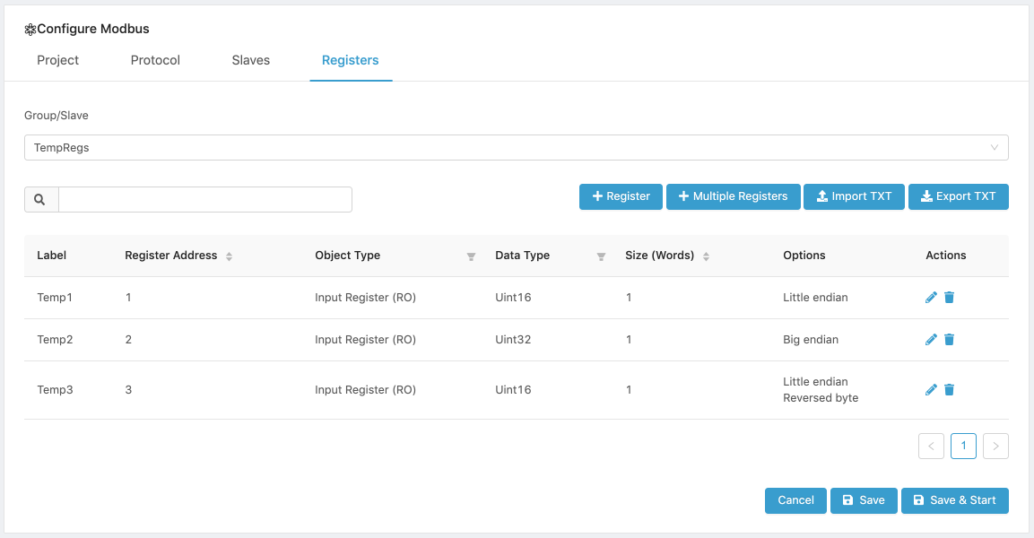
Configuring a Single Register
To Add a single Register, its Label, Register Address, Object Type, Data Type, Size and Options need to be configured or left with default values. To set up the register with your values:
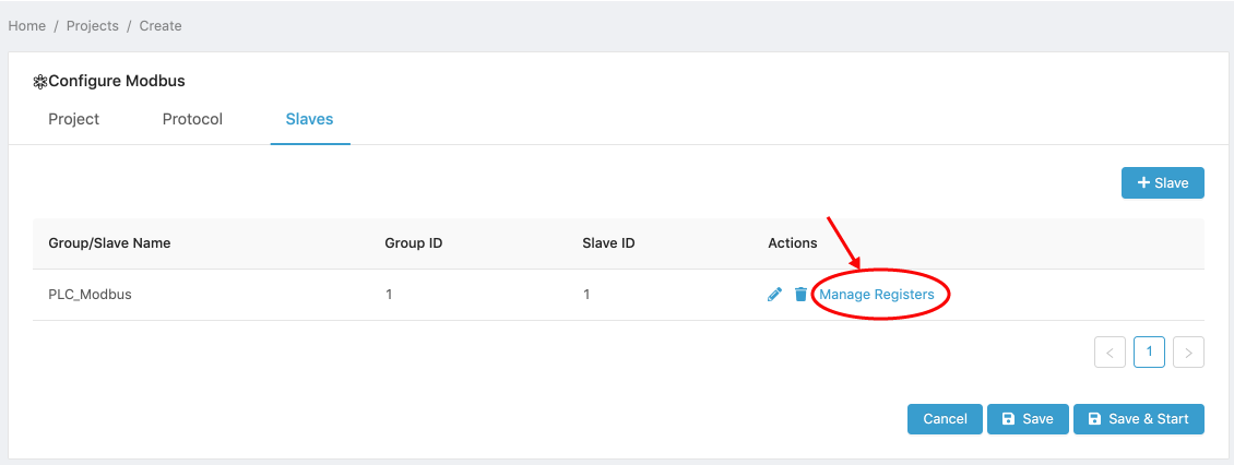
- Open the Groups tab and click on Manage registers.
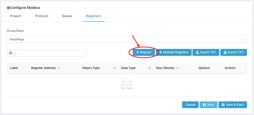
- Click on the [ Register ] button.
-
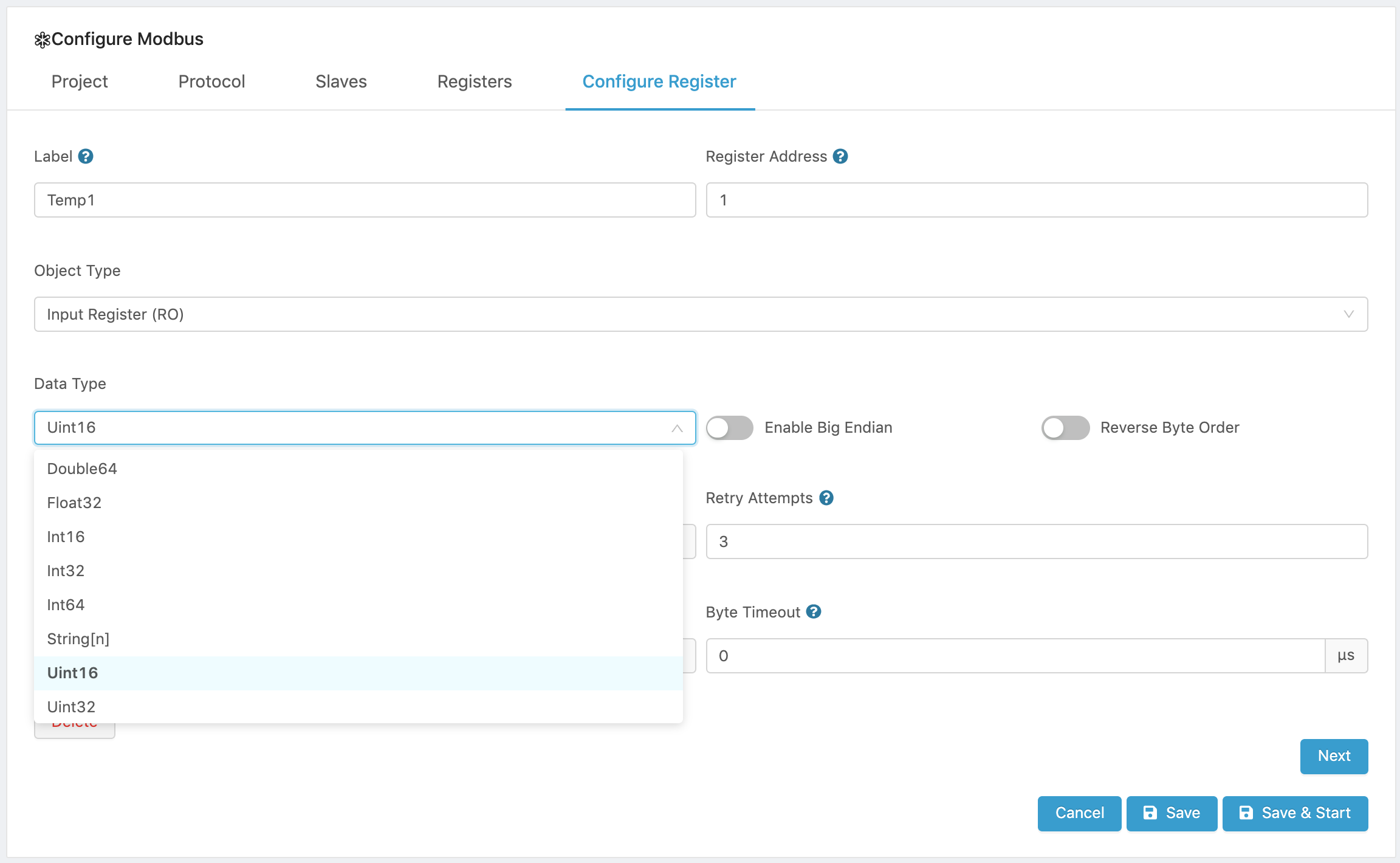
Enter a Label to name your register.
-
Enter a valid 16-bit register address (0 - 65,535).
-
Configure the Data Parameters.
Select and configure the parameters that apply to your data set.
Please note that Data Type and Byte order parameters apply only to Input and Holding registers. Coils and Discrete Inputs are only one bit long and, therefore, these parameters do not apply to them. Size applies to all Object types.
- Select a Data type:
Data Type Description Bitfield16 (unpacked) Unpacked data structure with a sequence of 16-bits. Allows to add a label to every one of the 16 bits. Bitfield16 Packed data structure that holds a sequence of 16-bits. A single value represents the 16-bits. Bitfield32 (unpacked) Unpacked data structure with a sequence of 32-bits. Allows to add a label to every one of the 32 bits. Bitfield32 - Packed Packed data structure that holds a sequence of 32-bits. A single value represents the 32-bits. Byte [<n>] An array of raw values with no defined meaning. Double64 Double precision floating point values. Float32 32-bit floating point values. Int16 16-bit integer. Int32 32-bit integer. Int64 64-bit integer. String[<n>] Array of character values. Uint32 Unsigned 32-bit integer. Uint64 Unsigned 64-bit integer.
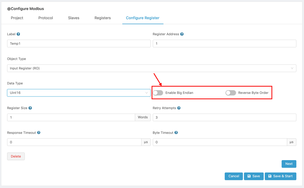
- Configure the byte order parameters.
- To use Big Endian and send the most significant byte first, turn on the Big Endian switch. The default is Little Endian.
- To reverse the byte order, turn on the Reverse Byte order switch. The default is normal order.
- Configure the Register size.
- Register sizes are expressed in number of words. Words are 2 bytes, or 16 bits long. The register will start at the address specified, and will have the size set by this parameter.
- Please note that the size must be multiple of the data type selected. For example, for Double64, the minimum size is 4 and any size set must be a multiple of 4. For Int32 the minimum size is 2, and any size set must be a multiple fo 2. For Bitfield16, the minimum size is 1, and the size is any multiple of 1.

- Optionally, enter a starting value for the register. This parameter can be very useful if you want to use the register
- A sample configuration is shown below.
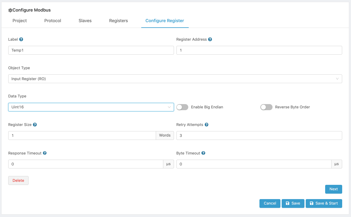
- Once you have finished configuring the register, you have two options:
- Click Next to continue with the configuration of your device and view your register in the Registers tab, or
- Click Delete to delete the register you just created.
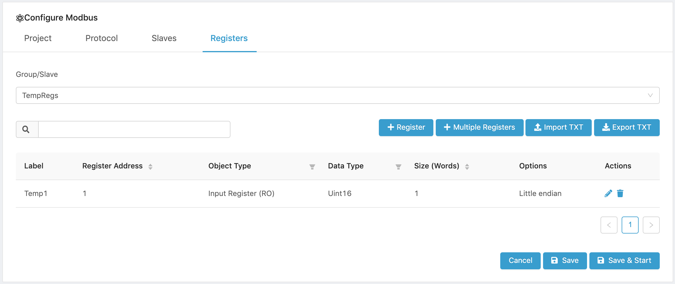
- When you are back in the Registers tab, you have several options:
- Add additional single registers or multiple registers.
- Click Save to save your work.
- Click Save and Restart to save your configuration and run the Modbus module. If the module was previously configured and running, it will be stopped and restarted with the new configuration.
- Configure the IoT cloud communications parameters by creating or configuring a Message Router project that will specify the data source for the Slave.
Editing a Register
To edit a register:
- Open the Registers tab.
- Select the register to edit and click on the Edit ( ) icon.
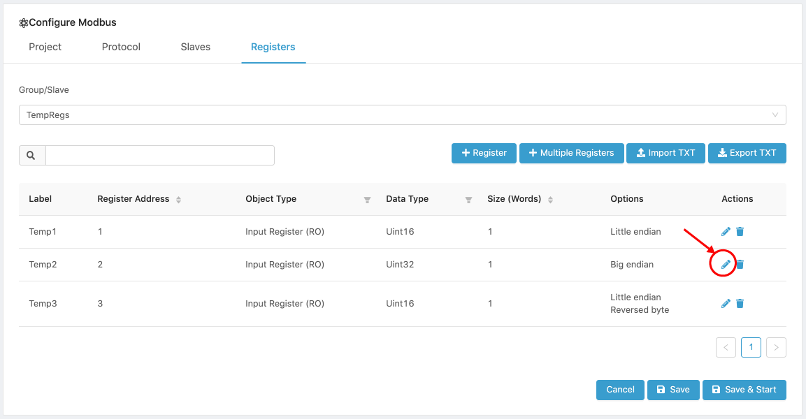
-
Configure the register as indicated in the Configuring a Single Register section.
-
Press the Save button to save the changes, or the Save and Restart button to save and run the Modbus module. If the module was previously configured and running, it will be stopped and restarted with the new register configuration.
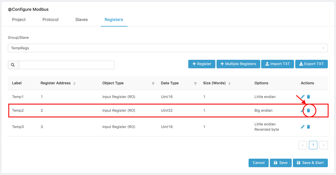
Deleting a Register
There are two ways to delete a register:
- Deleting it from the Register list.
- Open the Registers tab.
- Select the register.
- Click on the Delete ( ) icon.
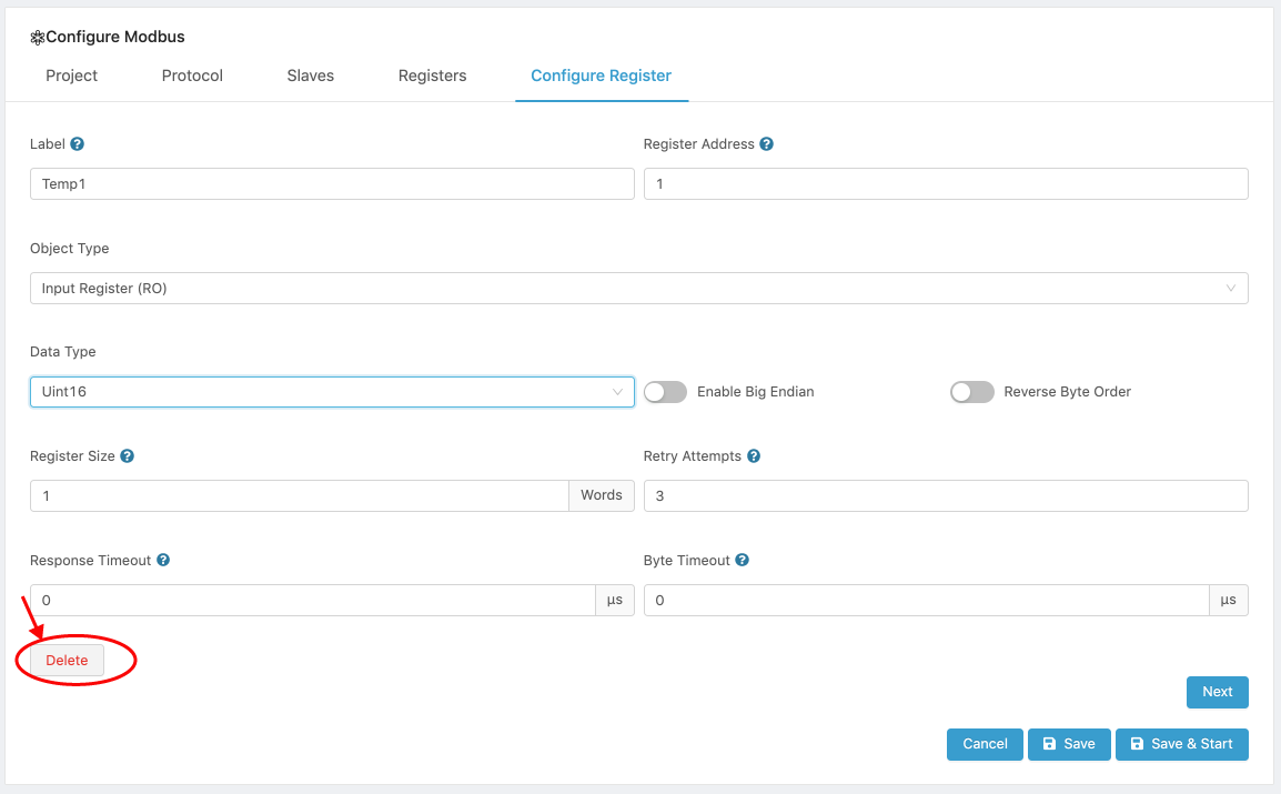
- Opening the register and deleting it.
- Open the Registers tab.
- Select the register.
- Click on the Edit ( ) icon.
- Click on the Delete button on the lower left hand side of the register configuration panel.
Adding Multiple Registers
The Modbus module allows to configure multiple registers with similar characteristics with one set of parameters. Multiple registers can be added to your existing registers.
When adding multiple registers, their Labels, Number of Registers, starting Register Address, Object Type, Data Type, Size, Object Type and Options need to be configured or left with default values, if applicable.
Once the registers are added, they can be individually edited by selecting them from their Map’s register list and clicking on the Edit icon ( ) to configure specific parameters, if desired.
To add multiple registers:
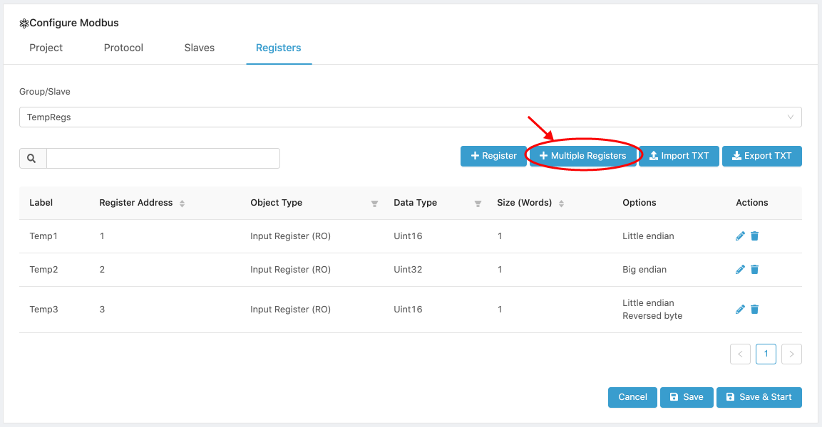
- Open the Registers tab.
- Click on the [ Multiple Registers ] button.
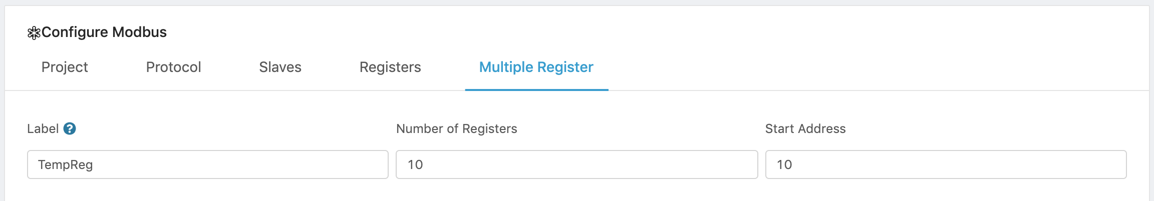
- Enter a Label to name your registers. The register labels will have labels of the format Label#, where # is replaced by the register number.
- Enter the number of registers to be created.
- Enter a valid 16-bit starting address (0 - 65,535). The new registers will have addresses including and following the starting address.
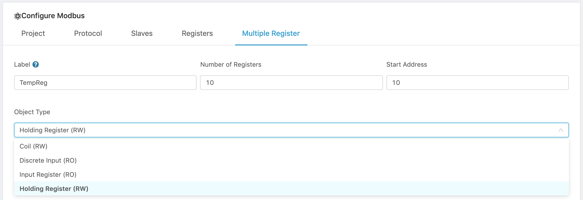
- Configure the Object Type. The following types of registers are supported:
Object Type Access Size Coil Read-write 1 bit Discrete Input Read-only 1 bit Input register Read-only 16 bits Holding register Read-write 16 bits
- Configure the Data Parameters.
Select and configure the parameters that apply to your data set.
Please note that Data Type and Byte order parameters apply only to Input and Holding registers. Coils and Discrete Inputs are only one bit long and, therefore, these parameters do not apply to them. Size applies to all Object types.
- Select a Data type:
Data Type Description Bitfield16 (unpacked) Unpacked data structure with a sequence of 16-bits. Allows to add a label to every one of the 16 bits. Bitfield16 Packed data structure that holds a sequence of 16-bits. A single value represents the 16-bits. Bitfield32 (unpacked) Unpacked data structure with a sequence of 32-bits. Allows to add a label to every one of the 32 bits. Bitfield32 - Packed Packed data structure that holds a sequence of 32-bits. A single value represents the 32-bits. Byte [<n>] An array of raw values with no defined meaning. Double64 Double precision floating point values. Float32 32-bit floating point values. Int16 16-bit integer. Int32 32-bit integer. Int64 64-bit integer. String[<n>] Array of character values. Uint32 Unsigned 32-bit integer. Uint64 Unsigned 64-bit integer.
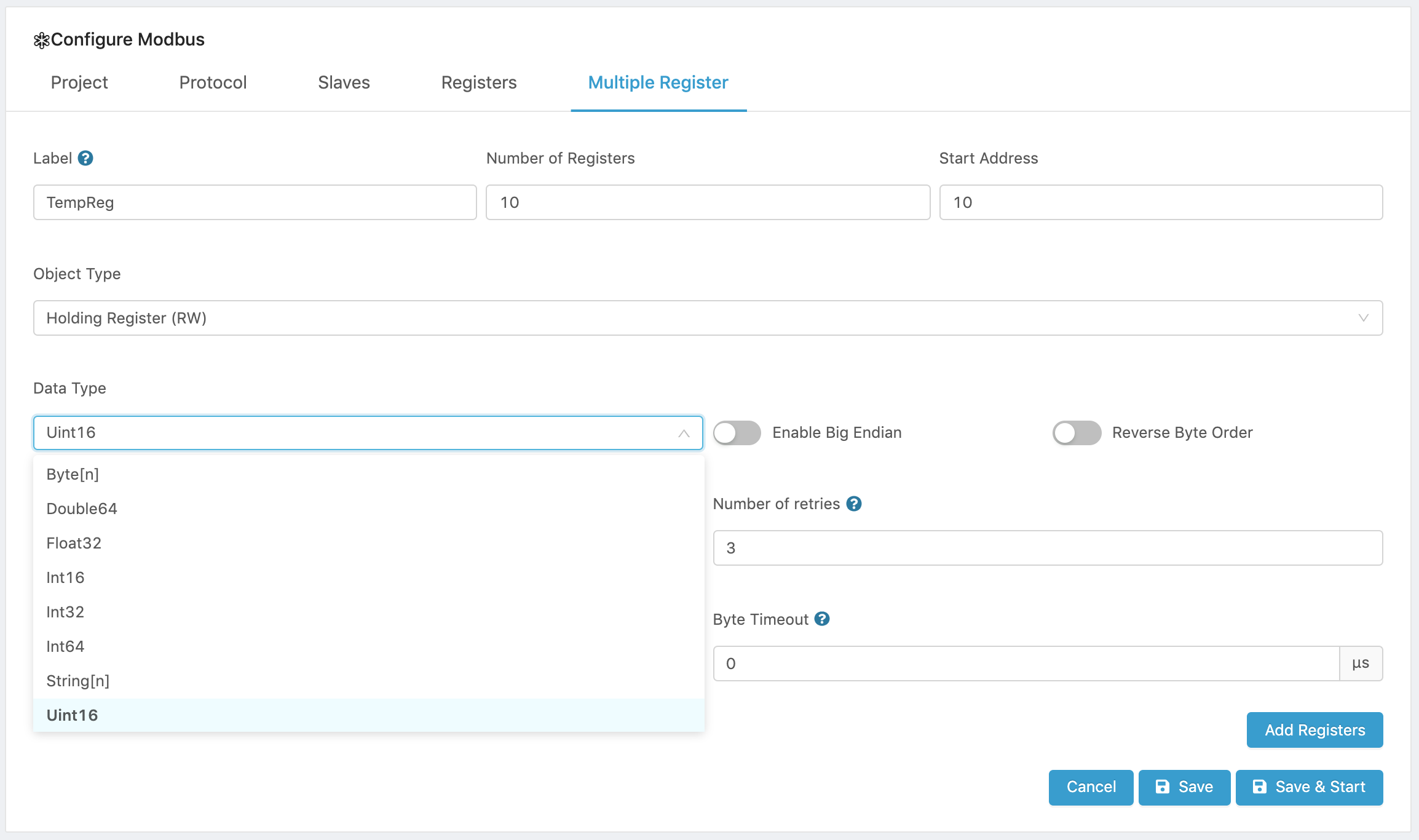
- Configure the byte order parameters.
- To use Big Endian turn on the Big Endian switch. The default is Little Endian.
- To reverse the byte order, turn on the Reverse Byte order switch. The default is normal order.
- Configure the Register size.
- Register sizes are expressed in number of words. Words are 2 bytes, or 16 bits long. The register will start at the address specified, and will have the size set by this parameter.
- Please note that the size must be multiple of the data type selected. For example, for Double64, the minimum size is 4 and any size set must be a multiple of 4. For Int32 the minimum size is 2, and any size set must be a multiple fo 2. For Bitfield16, the minimum size is 1, and the size is any multiple of 1.
- Configure the Connection Parameters.
The following connection parameters can be configured.
- Retry Attempts. Number of times the master will retry to poll the register when there are errors.
- Response Timeout. Time interval in microseconds to wait for the response from a Modbus slave.
- Byte Timeout. Time interval in microseconds to wait for a byte from a Modbus slave.
-
Click Add Registers to create the registers and view them in the Register tab.
-
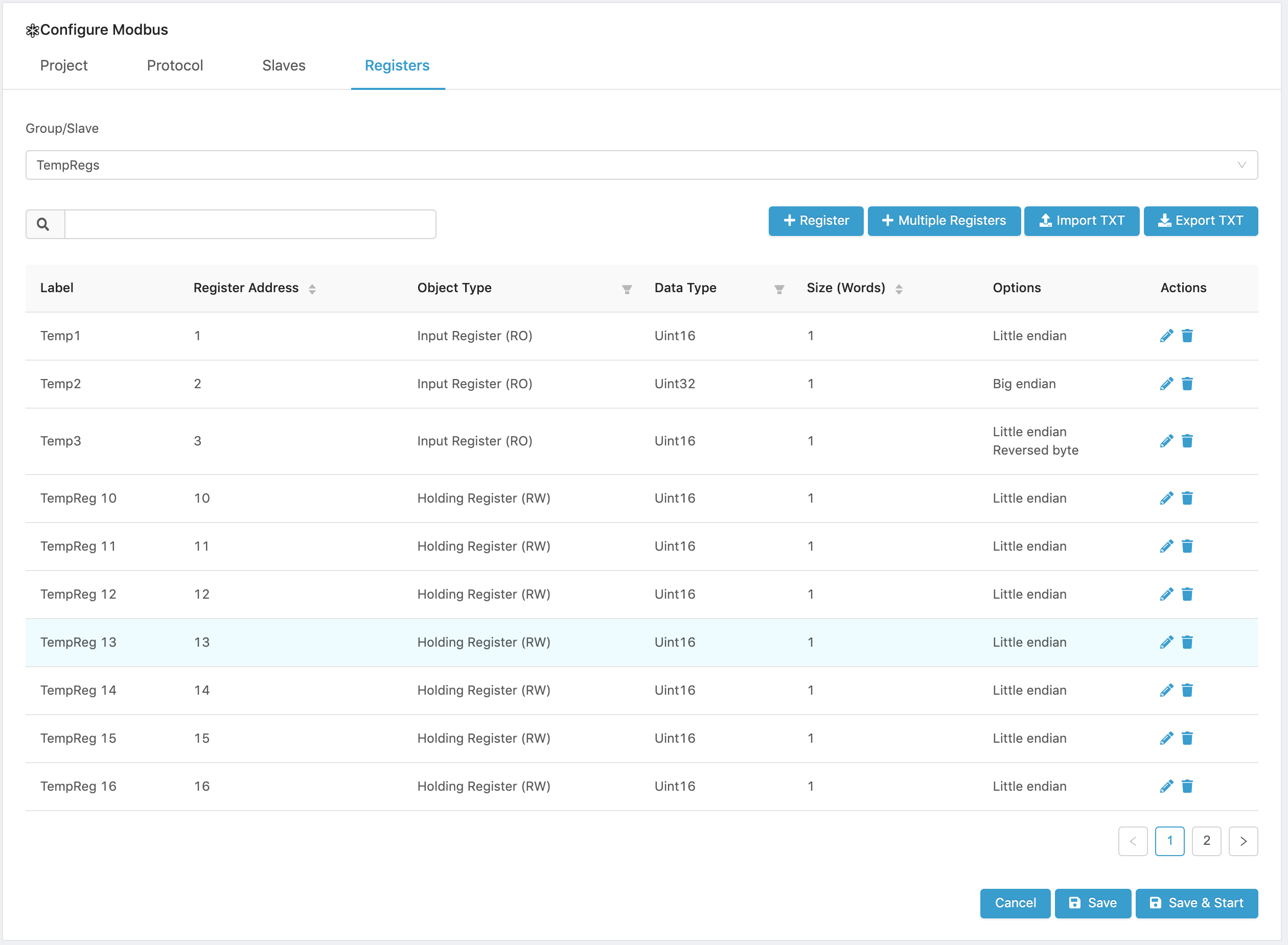
Confirm that the registers were created successfully in the Registers tab.. In the example below, there was an existing register called Register1 and the 10 additional registers were added below it.
-
Save to save your Project, or
-
Save and Restart to Save your configuration and Run your Modbus Project. If the Modbus Project was previously configured and running, it will be stopped and restarted with the new configuration.
-
Configure the IoT cloud communications parameters by creating or configuring a Message Router project.
Importing Slave/Group Registers
You can import register configurations from a Tab Delimited Text file.
WARNING!
Any existing registers will be deleted and replaced by the imported registers.
To preserve existing registers, Export them as a CSV file and add the exported data to the file to be imported.
The file must conform to the following data structure and must have a header row whose values are ignored, where <tab> is the tab character.
Register Label<tab>Register Address<tab>Object Type<tab>Data Type<tab>Enable Big Endian<tab>Reverse Byte Order<tab>Register Size<tab>Number of Retries<tab>Response Timeout<tab>Byte Timeout
Only tab “\tab” separators are supported, and there can only be one tab between each field. The import function is used for multiple modules and some of the connector variables support support value strings with commas; therefore, only Tab Delimited Text files are supported.
Note that any existing registers in the Group / Slave selected for the import will be replaced by the imported registers.
To import a register configuration file:
- Open the Registers tab.
-
Click on the [ Import ] button to open the Import Registers tab.
-
Read the Instructions and click on the [ Upload file ] button.
-
Select a valid Tab Delimited Text file and complete the upload.
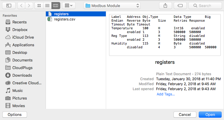
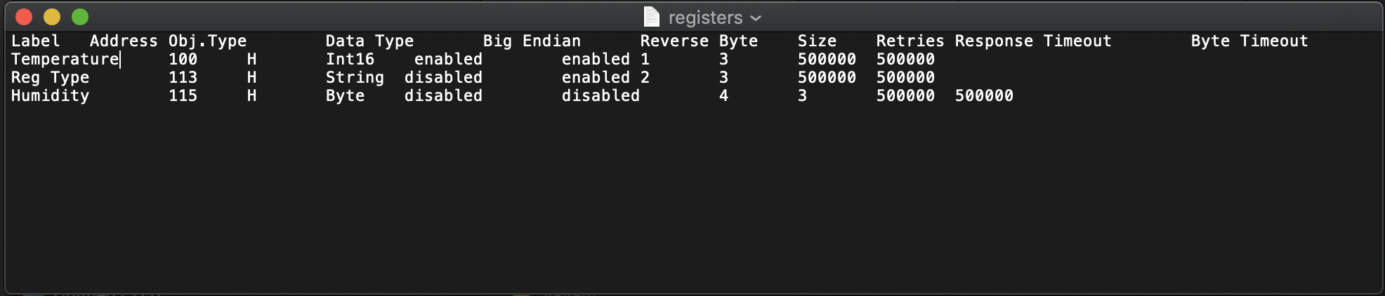
The text file has the tab delimited data shown below, and it was created with a standard text editor.
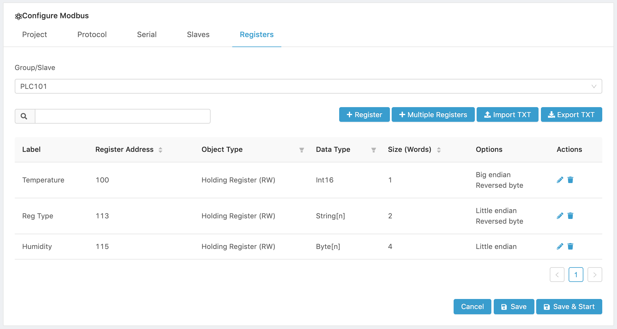
- Verify that the registers were imported correctly by opening the Registers tab.
- Configure the IoT cloud communications parameters by creating or configuring a Message Router project.
Exporting Slave/Group Registers
You can export register configurations in a Tab Delimited Text file.
The file will conform to the following data structure and will have a header row, where <tab> is the tab character.
Register Label<tab>Register Address<tab>Object Type<tab>Data Type<tab>Enable Big Endian<tab>Reverse Byte Order<tab>Register Size<tab>Number of Retries<tab>Response Timeout<tab>Byte Timeout
Only tab “\tab” separators are supported, and there will only be one tab between each field.
To export a register configuration file:
- Open the Registers tab.
-
Click on the [ Export ] button to open the Export Registers tab.
-
Read the Instructions and click on the ( Download file ) button.
-
Enter a name for the Tab Delimited Text file, or use the default and Click OK to initiate the download.
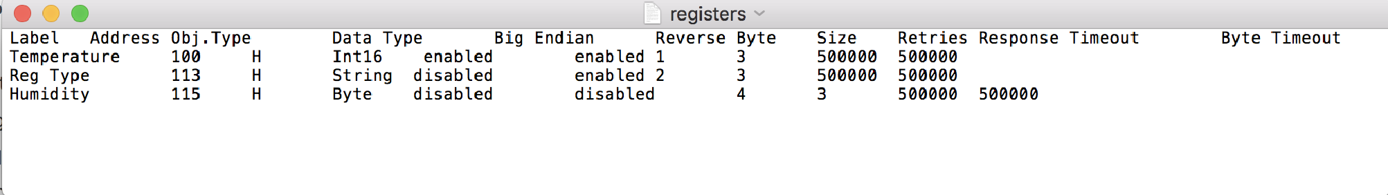
The text file has the tab delimited data shown below. It was open with a standard text editor.