1. Modbus Overview
 |
Modbus is one of the most prolific automation and control protocols. The Edge One™ Platform Modbus Module enables integration of Modbus devices and PLC’s with Edge One™, the CloudPlugs IIoT platform and other supported IoT cloud services. |
|---|
This guide includes:
- Information on the Modbus protocol.
- A description of the Edge One™ Modbus module, and
- The Modbus Module Data Structure.
To learn how to configure the Edge One™ Modbus module, please refer to the Modbus Getting Started Guide.
The Modbus Protocol
Modbus is a serial communications protocol originally published by Modicon (now Schneider Electric) in 1979 for use with its programmable logic controllers (PLCs). Since Modbus is simple, robust, openly published and royalty free, it has since become a de facto standard communication protocol for connecting industrial electronic devices.
Modbus enables communication among many devices connected to the same network, for example a system that measures temperature and humidity and communicates the results to a computer. Modbus is often used to connect a supervisory computer with a remote terminal unit (RTU) in supervisory control and data acquisition (SCADA) systems. Many of the data types are named from its use in driving relays: a single-bit physical output is called a coil, and a single-bit physical input is called a discrete input or a contact.
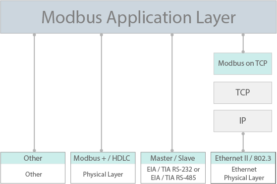
Modbus is considered an application layer messaging protocol, providing Master/Slave communication between devices connected together through buses or networks. On the OSI model, Modbus is positioned at level 7. As an application layer protocol, it defines rules for organizing and interpreting data, but remains simply a messaging structure, independent of the underlying physical layer. Since it is easy to understand, freely available, and accessible to anyone, it is widely supported by many manufacturers.
 |
|---|
| Figure 2. Modbus Communications Stack |
|---|
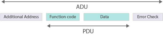
The Modbus protocol defines a simple Protocol Data Unit (PDU) independent of the underlying communication layers. Modbus is intended to be a request/reply protocol and delivers services specified by function codes. The function codes of Modbus are elements of Modbus’ request/reply PDUs.The mapping of Modbus protocol on specific buses or network can introduce some additional fields on the Application Data Unit (ADU). In order to build the Modbus application data unit (ADU), the client must initiate a Modbus transaction. It is the function code which informs the server as to which type of action to perform. The format of a request initiated by a Master is established by the Modbus application protocol. The function code field is then coded into one byte. Only codes within the range of 1 through 255 are considered valid, with 128-255 being reserved for exception responses. When the Master sends a message to the Slave, it is the function code field which informs the server of what type of action to perform.
 |
|---|
| Figure 3. General Modbus Frame |
|---|
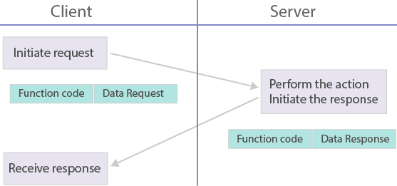
In Modbus communications, only one device (the master/client) can initiate transactions (called queries). The other devices (slaves/servers) respond by supplying the requested data to the Master, or by taking the action requested in the query. A Slave is any peripheral device (I/O transducer, valve, network drive, or other measuring device) which processes information and sends its output to the Master using Modbus. A typical Master device is a host computer running appropriate application software such as the CloudPlugs Edge One™ Modbus module. Other devices may function as both clients (masters) and servers (slaves).
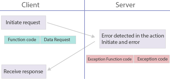
Masters can address individual slaves, or can initiate a broadcast message to all slaves. Slaves return a response to all queries addressed to them individually, but do not respond to broadcast queries. Slaves do not initiate messages on their own, they only respond to queries from the Master. A Master’s query will consist of a slave address (or broadcast address), a function code defining the requested action, any required data, and an error checking field. A slave’s response consists of fields confirming the action taken, any data to be returned, and an error checking field. Note that the query and response both include a device address, a function code, plus applicable data, and an error checking field. If no error occurs, the slave’s response contains the data as requested. If an error occurs in the query received, or if the slave is unable to perform the action requested, the slave will return an exception message as its response (see Modbus Exceptions in the Modbus documentation.) The error check field of the slave’s message frame allows the Master to confirm that the contents of the message are valid. Traditional Modbus messages are transmitted serially and parity checking is also applied to each transmitted character in its data frame. The following images show the flow of an error free transaction and one with error.
 |
 |
|---|
| Figure 4. Modbus Transaction (error free) | Figure 5. Modbus Transaction (exception response) |
|---|
The development and update of Modbus protocols has been managed by the Modbus Organization since April 2004 who seeks to drive the adoption and evolution of Modbus. To learn more, please refer to the Modbus Technical Resources Documentation.
Edge One™ Modbus Module
The Edge One™ Modbus module is supplied as a container that enables bi-directional communications and read/write operations of the Edge One™ platform with Modbus devices. Data collected from Modbus field devices can be processed locally by the optional Edge One™ Flows module, by a SmartPlug™ application or another containerized application, and it is then sent to the CloudPlugs cloud, or a supported public cloud.
The Edge One™ Modbus module publishes Modbus register values into CloudPlugs channels making them available to other devices and applications subscribing to those channels. All the communications with supervisory applications in the cloud are encrypted, event driven and asynchronous, resulting in substantial traffic savings.
A single Edge One™ deployment can operate as a Modbus Master and as a Modbus Slave, if desired.
The Modbus Module for the Edge One™ platform supports the following configurations in Master and/or Slave modes:
- Modbus RTU (Remote Terminal Unit) (Default) - used in serial communication and makes use of a compact, binary representation of the data for protocol communication. The RTU format follows the commands/data with a cyclic redundancy check checksum as an error check mechanism to ensure the reliability of data. Modbus RTU is the most common implementation available for Modbus. A Modbus RTU message must be transmitted continuously without inter-character hesitations. Modbus messages are framed (separated) by idle (silent) periods. This selection requires the setup of several serial parameters.
- Modbus TCP - used for communications over TCP/IP networks, connecting over port 502. It does not require a checksum calculation, as lower layers already provide checksum protection.
- Modbus RTU over TCP - a Modbus variant that differs from Modbus TCP in that a checksum is included in the payload as with Modbus RTU.
In addition, the following object types can be configured:
| Object Type | Access | Size |
|---|---|---|
| Coil | Read-Write | 1-bit |
| Discrete Input | Read-Only | 1-bit |
| Input Register | Read-Only | 16-bit |
| Holding Register | Read-Write | 16-bit |
To learn how to configure the Edge One™ Modbus module, please refer to the Get Started Guide.
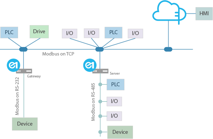
The image below depicts a possible deployment of the CloudPlugs Edge One™ configured for Master RTU, and TCP operations. Note that the HMI can be run locally and on a web/mobile control application through the cloud.
 |
|---|
| Figure 1. Sample Edge One™ Modbus Network Architecture |
|---|
Modbus Module Data Structure
The Edge One™ Modbus Module uses the standard data representation of all Edge One™ modules.
Slave register data is stored in JSON, key-value pairs in which the key is the register address and the value is the value of the register.
Modbus Slaves are represented as Groups and have three identifiers:
- Group/Slave Name, a string that represents the custom name that is entered for the Slave (also called a Group).
- Group ID, a number that will be used to identify the Slave inside the Edge One™ data structure.
- Slave ID, a number that indicates the ID of the Slave in the Modbus communication structure.
The MQTT topics carrying Modbus payloads have the following structure:
topic:  modbus/PID/GID

where,

	modbus  indicates that this is a modbus module.
	PID		a number or Project ID that identifies the Modbus project generating data
	GID		a number or Group ID as indicated above

The data inside this topic is a JSON such as:

{
   "100": 25,
   "200": 34
}

Register address 100 has a value of 25, and register address 200 has a value of 34.
Data can be read locally or sent to a remote MQTT server or cloud such as CloudPlugs IoT using the Message Router